Electronic filters are a type of signal processing filter in the form of electrical circuits. This article covers those filters consisting of lumped electronic components, as opposed to distributed-element filters. That is, using components and interconnections that, in analysis, can be considered to exist at a single point. These components can be in discrete packages or part of an integrated circuit.
Television signal splitter consisting of a high-pass filter (left) and a low-pass filter (right). The antenna is connected to the screw terminals to the left of center.
Distributed-element filter
A distributed-element filter is an electronic filter in which capacitance, inductance, and resistance are not localised in discrete capacitors, inductors, and resistors as they are in conventional filters. Its purpose is to allow a range of signal frequencies to pass, but to block others. Conventional filters are constructed from inductors and capacitors, and the circuits so built are described by the lumped element model, which considers each element to be "lumped together" at one place. That model is conceptually simple, but it becomes increasingly unreliable as the frequency of the signal increases, or equivalently as the wavelength decreases. The distributed-element model applies at all frequencies, and is used in transmission-line theory; many distributed-element components are made of short lengths of transmission line. In the distributed view of circuits, the elements are distributed along the length of conductors and are inextricably mixed together. The filter design is usually concerned only with inductance and capacitance, but because of this mixing of elements they cannot be treated as separate "lumped" capacitors and inductors. There is no precise frequency above which distributed element filters must be used but they are especially associated with the microwave band.

Figure 1. A circuit featuring many of the filter structures described in this article. The operating frequency of the filters is around 11 gigahertz (GHz). This circuit is described in the box below.
The PCB inside a 20GHz Agilent N9344C spectrum analyser showing various microstrip distributed-element filter technology elements
Figure 2. A parallel-coupled lines filter in microstrip construction
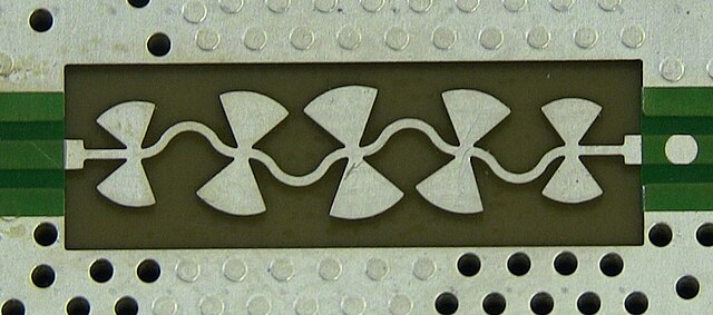
A microstrip low pass filter implemented with bowtie stubs inside a 20 GHz Agilent N9344C spectrum analyser


