1.
GigE Vision
–
GigE Vision is an interface standard introduced in 2006 for high-performance industrial cameras. It provides a framework for transmitting high-speed video and related control data over Ethernet networks, the distribution of software or development, manufacture or sale of hardware that implement the standard, require the payment of annual licensing fees. However, Imaging Source, one of the GigE camera producers, the standard was initiated by a group of 12 companies, and the committee has since grown to include more than 50 members. The 12 founding members were, Adimec, Atmel, Basler AG, CyberOptics, Teledyne DALSA, JAI A/S, JAI PULNiX, Matrox, National Instruments, Photonfocus, Pleora Technologies, the Automated Imaging Association oversees the ongoing development and administration of the standard. GigE Vision is based on the Internet Protocol standard, one goal is to unify current protocols for industrial cameras. The other is to make it easier for 3rd party organizations to develop software and hardware. GigE Vision has four elements, GigE Vision Control Protocol —Runs on the UDP protocol. The standard defines how to control and configure devices, specifies stream channels and the mechanisms of sending image and configuration data between cameras and computers. GigE Vision Stream Protocol —Runs on the UDP protocol, covers the definition of data types and the ways images can be transferred via GigE. GigE Device Discovery Mechanism—Provides mechanisms to obtain IP addresses, XML description file based on a schema defined by the European Machine Vision Associations GenICam standard that allows access to camera controls and image streams
2.
Conventional PCI
–
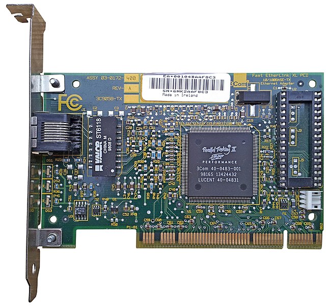
Conventional PCI, often shortened to PCI, is a local computer bus for attaching hardware devices in a computer. PCI is the initialism for Peripheral Component Interconnect and is part of the PCI Local Bus standard, the PCI bus supports the functions found on a processor bus but in a standardized format that is independent of any particular processors native bus. Devices connected to the PCI bus appear to a bus master to be connected directly to its own bus and are assigned addresses in the address space. It is a bus, synchronous to a single bus clock. Attached devices can take either the form of an integrated circuit fitted onto the motherboard itself or a card that fits into a slot. The PCI Local Bus was first implemented in IBM PC compatibles and it has subsequently been adopted for other computer types. Typical PCI cards used in PCs include, network cards, sound cards, modems, extra ports such as USB or serial, TV tuner cards, PCI video cards replaced ISA and VESA cards until growing bandwidth requirements outgrew the capabilities of PCI. The preferred interface for video cards then became AGP, itself a superset of conventional PCI and these have one locating notch in the card. Version 2.0 of the PCI standard introduced 3.3 V slots, universal cards, which can operate on either voltage, have two notches. Version 2.1 of the PCI standard introduced optional 66 MHz operation, a server-oriented variant of conventional PCI, called PCI-X operated at frequencies up to 133 MHz for PCI-X1.0 and up to 533 MHz for PCI-X2.0. An internal connector for laptop cards, called Mini PCI, was introduced in version 2.2 of the PCI specification, the PCI bus was also adopted for an external laptop connector standard – the CardBus. The first PCI specification was developed by Intel, but subsequent development of the standard became the responsibility of the PCI Special Interest Group, Conventional PCIs heyday in the desktop computer market was approximately 1995–2005. PCI and PCI-X have become obsolete for most purposes, however, they are common on modern desktops for the purposes of backwards compatibility. Many kinds of devices available on PCI expansion cards are now commonly integrated onto motherboards or available in USB. Work on PCI began at Intels Architecture Development Lab c. 1990, a team of Intel engineers defined the architecture and developed a proof of concept chipset and platform partnering with teams in the companys desktop PC systems and core logic product organizations. PCI was immediately put to use in servers, replacing MCA, in mainstream PCs, PCI was slower to replace VESA Local Bus, and did not gain significant market penetration until late 1994 in second-generation Pentium PCs. By 1996, VLB was all but extinct, and manufacturers had adopted PCI even for 486 computers, EISA continued to be used alongside PCI through 2000. Apple Computer adopted PCI for professional Power Macintosh computers in mid-1995, the 64-bit version of plain PCI remained rare in practice though, although it was used for example by all G3 and G4 Power Macintosh computers
3.
Network interface controller
–
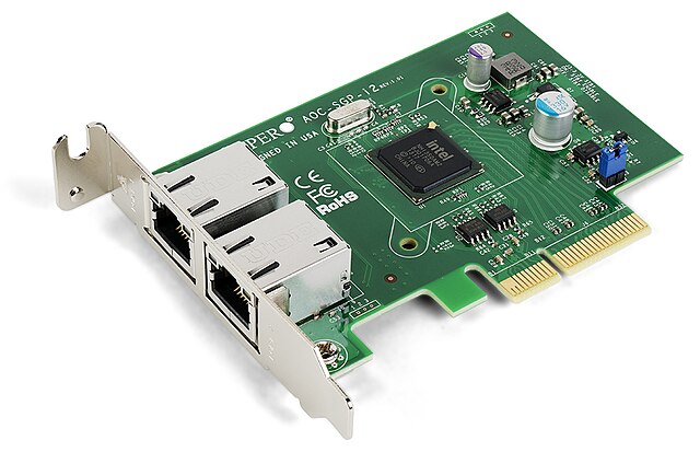
A network interface controller is a computer hardware component that connects a computer to a computer network. Early network interface controllers were commonly implemented on expansion cards that plugged into a computer bus, the low cost and ubiquity of the Ethernet standard means that most newer computers have a network interface built into the motherboard. The network controller implements the electronic circuitry required to communicate using a physical layer and data link layer standard such as Ethernet, Fibre Channel. The NIC allows computers to communicate over a network, either by using cables or wirelessly. Although other network technologies exist, IEEE802 networks including the Ethernet variants have achieved near-ubiquity since the mid-1990s, newer server motherboards may even have dual network interfaces built-in. The Ethernet capabilities are integrated into the motherboard chipset or implemented via a low-cost dedicated Ethernet chip. A separate network card is not required unless additional interfaces are needed or some type of network is used. The NIC may use one or more of the techniques to indicate the availability of packets to transfer. Interrupt-driven I/O is where the peripheral alerts the CPU that it is ready to transfer data, also, NICs may use one or more of the following techniques to transfer packet data, Programmed input/output is where the CPU moves the data to or from the NIC to memory. Direct memory access is where some other device other than the CPU assumes control of the bus to move data to or from the NIC to memory. This removes load from the CPU but requires more logic on the card, in addition, a packet buffer on the NIC may not be required and latency can be reduced. There are two types of DMA, third-party DMA in which a DMA controller other than the NIC performs transfers, an Ethernet network controller typically has an 8P8C socket where the network cable is connected. Older NICs also supplied BNC, or AUI connections, a few LEDs inform the user of whether the network is active, and whether or not data transmission occurs. Ethernet network controllers typically support 10 Mbit/s Ethernet,100 Mbit/s Ethernet, such controllers are designated as 10/100/1000, meaning that they can support a notional maximum transfer rate of 10,100 or 1000 Mbit/s. 10 Gigabit Ethernet NICs are also available, and, as of November 2014, are beginning to be available on computer motherboards, multiqueue NICs provide multiple transmit and receive queues, allowing packets received by the NIC to be assigned to one of its receive queues. The hardware-based distribution of the interrupts, described above, is referred to as receive-side scaling, purely software implementations also exist, such as the receive packet steering and receive flow steering. Examples of such implementations are the RFS and Intel Flow Director, with multiqueue NICs, additional performance improvements can be achieved by distributing outgoing traffic among different transmit queues. By assigning different transmit queues to different CPUs/cores, various operating systems internal contentions can be avoided and those NICs support, Accessing local and remote memory without involving the remote CPU
4.
Computer network
–
A computer network or data network is a telecommunications network which allows nodes to share resources. In computer networks, networked computing devices exchange data with other using a data link. The connections between nodes are established using either cable media or wireless media, the best-known computer network is the Internet. Network computer devices that originate, route and terminate the data are called network nodes, nodes can include hosts such as personal computers, phones, servers as well as networking hardware. Two such devices can be said to be networked together when one device is able to exchange information with the other device, Computer networks differ in the transmission medium used to carry their signals, communications protocols to organize network traffic, the networks size, topology and organizational intent. In most cases, application-specific communications protocols are layered over other more general communications protocols and this formidable collection of information technology requires skilled network management to keep it all running reliably. The chronology of significant computer-network developments includes, In the late 1950s, in 1960, the commercial airline reservation system semi-automatic business research environment went online with two connected mainframes. Licklider developed a group he called the Intergalactic Computer Network. In 1964, researchers at Dartmouth College developed the Dartmouth Time Sharing System for distributed users of computer systems. The same year, at Massachusetts Institute of Technology, a group supported by General Electric and Bell Labs used a computer to route. Throughout the 1960s, Leonard Kleinrock, Paul Baran, and Donald Davies independently developed network systems that used packets to transfer information between computers over a network, in 1965, Thomas Marill and Lawrence G. Roberts created the first wide area network. This was an precursor to the ARPANET, of which Roberts became program manager. Also in 1965, Western Electric introduced the first widely used telephone switch that implemented true computer control, in 1972, commercial services using X.25 were deployed, and later used as an underlying infrastructure for expanding TCP/IP networks. In July 1976, Robert Metcalfe and David Boggs published their paper Ethernet, Distributed Packet Switching for Local Computer Networks, in 1979, Robert Metcalfe pursued making Ethernet an open standard. In 1976, John Murphy of Datapoint Corporation created ARCNET, a network first used to share storage devices. In 1995, the transmission speed capacity for Ethernet increased from 10 Mbit/s to 100 Mbit/s, by 1998, Ethernet supported transmission speeds of a Gigabit. Subsequently, higher speeds of up to 100 Gbit/s were added, the ability of Ethernet to scale easily is a contributing factor to its continued use. Providing access to information on shared storage devices is an important feature of many networks, a network allows sharing of files, data, and other types of information giving authorized users the ability to access information stored on other computers on the network
5.
Ethernet frame
–
A data packet on an Ethernet link is called an Ethernet packet, which transports an Ethernet frame as its payload. An Ethernet frame is preceded by a preamble and start frame delimiter, each Ethernet frame starts with an Ethernet header, which contains destination and source MAC addresses as its first two fields. The middle section of the frame is payload data including any headers for other protocols carried in the frame, the frame ends with a frame check sequence, which is a 32-bit cyclic redundancy check used to detect any in-transit corruption of data. A data packet on the wire and the frame as its payload consist of binary data, Ethernet transmits data with the most-significant octet first, within each octet, however, the least-significant bit is transmitted first. The internal structure of an Ethernet frame is specified in IEEE802.3, the table below shows the complete Ethernet packet and the frame inside, as transmitted, for the payload size up to the MTU of 1500 octets. Some implementations of Gigabit Ethernet and other higher-speed variants of Ethernet support larger frames, the optional 802. 1Q tag consumes additional space in the frame. Field sizes for this option are indicated parenthetically in the table above, IEEE802. 1ad allows for multiple tags in each frame. This option is not illustrated here, an Ethernet packet starts with a seven-octet preamble and one-octet start frame delimiter. The preamble consists of a 56-bit pattern of alternating 1 and 0 bits, allowing devices on the network to easily synchronize their receiver clocks and it is followed by the SFD to provide byte-level synchronization and to mark a new incoming frame. The SFD is the value that marks the end of the preamble, which is the first field of an Ethernet packet. The SFD is designed to break the bit pattern of the preamble, the SFD is immediately followed by the destination MAC address, which is the first field in an Ethernet frame. SFD has the value of 171, which is transmitted with least-significant bit first as 213, physical layer transceiver circuitry is required to connect the Ethernet MAC to the physical medium. The connection between a PHY and MAC is independent of the medium and uses a bus from the media independent interface family. Fast Ethernet transceiver chips utilize the MII bus, which is a wide bus, therefore the preamble is represented as 14 instances of 0x5. Gigabit Ethernet transceiver chips use the GMII bus, which is a wide interface. The header features destination and source MAC addresses, the EtherType field and, optionally, the EtherType field is two octets long and it can be used for two different purposes. When used as EtherType, the length of the frame is determined by the location of the interpacket gap, the IEEE802. 1Q tag, if present, is a four-octet field that indicates virtual LAN membership and IEEE802. 1p priority. The minimum payload is 42 octets when an 802. 1Q tag is present and 46 octets when absent, the maximum payload is 1500 octets
6.
Fast Ethernet
–
In computer networking, Fast Ethernet is a collective term for a number of Ethernet standards that carry traffic at the nominal rate of 100 Mbit/s. Of the Fast Ethernet standards, 100BASE-TX is by far the most common, Fast Ethernet was introduced in 1995 as the IEEE802. 3u standard and remained the fastest version of Ethernet for three years before the introduction of Gigabit Ethernet. The acronym GE/FE is sometimes used for supporting both standards. Fast Ethernet is an extension of the 10-megabit Ethernet standard and it runs on UTP data or optical fiber cable in a star wired bus topology, similar to 10BASE-T where all cables are attached to a hub. Fast Ethernet devices are backward compatible with existing 10BASE-T systems. Fast Ethernet is sometimes referred to as 100BASE-X, where X is a placeholder for the FX, the standard specifies the use of CSMA/CD for media access control. A full-duplex mode is also specified and in all modern networks use Ethernet switches. The 100 in the type designation refers to the transmission speed of 100 Mbit/s. The letter following the dash refers to the medium that carries the signal. A Fast Ethernet adapter can be divided into a media access controller, which deals with the higher-level issues of medium availability. The MAC may be linked to the PHY by a four-bit 25 MHz synchronous parallel interface known as a media-independent interface, in rare cases the MII may be an external connection but is usually a connection between ICs in a network adapter or even within a single IC. The specs are based on the assumption that the interface between MAC and PHY will be a MII but they do not require it. Repeaters may use the MII to connect to multiple PHYs for their different interfaces, the MII fixes the theoretical maximum data bit rate for all versions of Fast Ethernet to 100 Mbit/s. 100BASE-T is any of several Fast Ethernet standards for twisted pair cables, including, 100BASE-TX, 100BASE-T4, the segment length for a 100BASE-T cable is limited to 100 metres. All are or were standards under IEEE802.3, almost all 100BASE-T installations are 100BASE-TX. In the early days of Fast Ethernet, much vendor advertising centered on claims by competing standards that said vendors standards will work better with existing cables than other standards. Thus most networks had to be rewired for 100 Megabit speed whether or not there had supposedly been CAT3 or CAT5 cable runs, 100BASE-TX is the predominant form of Fast Ethernet, and runs over two wire-pairs inside a category 5 or above cable. Like 10BASE-T, the pairs in a standard connection are terminated on pins 1,2,3 and 6
7.
Duplex (telecommunications)
–
A duplex communication system requires a pair of channels/frequencies hence the term duplex meaning two parts. The two channels are defined as uplink/downlink or reverse/forward, in a full-duplex system simultaneous transmission/reception is available, i. e. One can transmit and receive simultaneously, in a half-duplex system, each party can communicate with the other but not simultaneously, the communication is one direction at a time. Half duplex systems utilize separate channels for uplink and downlink, i. e. a transmit, in a half duplex communications system one user is allowed to transmit on the uplink channel at a time. The transmitted uplink signal is frequency translated via a radio/repeater to the downlink receive frequency which is received by all other radios tuned to the downlink/receive frequency. A half-duplex system is defined as system which operates two, hence duplex, dedicated uplink/downlink channels/frequencies. In a half duplex system a single path is provided for uplink, all uplink messages are broadcast via the downlink channel to all users simultaneously via a repeater which performs uplink to downlink channel/frequency translation. All cellular and land line PSTNs and PDSNs are full duplex systems, all full duplex systems require a channel/frequency translator via a radio/repeater. This is required in order to translate the uplink/transmit transmission from one to the downlink/receive channel/frequency of user two. Full duplex systems are one to one private systems unlike half duplex systems which broadcast to all users and this effectively makes the cable itself a collision-free environment and doubles the maximum total transmission capacity supported by each Ethernet connection. Time-division duplexing is commonly referred to as simplex communications, a single channel/frequency is employed for bidirectional communications. The term simplex communication as applied to TDM single channel systems predates the term TDD by at least 80 years, frequency-division duplexing as with any other duplex system is defined by two channel/frequency simultaneous communication. A channel/frequency pair are assigned to individual user on the system. An FDD system requires frequency translation from user 1 uplink/reverse frequency to user 2 downlink/forward frequency, full-duplex audio systems like telephones can create echo, which needs to be removed. Echo occurs when the coming out of the speaker, originating from the far end. The sound then reappears at the source end, but delayed. This feedback path may be acoustic, through the air, or it may be mechanically coupled, echo cancellation is a signal-processing operation that subtracts the far-end signal from the microphone signal before it is sent back over the network. Echo cancellation is important to the V.32, V.34, V.56, echo cancelers are available as both software and hardware implementations
8.
Ethernet hub
–
It has multiple input/output ports, in which a signal introduced at the input of any port appears at the output of every port except the original incoming. A hub works at the layer of the OSI model. Repeater hubs also participate in collision detection, forwarding a jam signal to all if it detects a collision. In addition to standard 8P8C ports, some hubs may also come with a BNC or Attachment Unit Interface connector to allow connection to legacy 10BASE2 or 10BASE5 network segments, hubs are now largely obsolete, having been replaced by network switches except in very old installations or specialized applications. As of 2011, connecting network segments by repeaters or hubs is deprecated by IEEE802.3, a network hub is an unsophisticated device in comparison with a switch. As a multiport repeater it works by repeating bits received from one of its ports to all other ports. It is aware of physical layer packets, that is it can detect their start, a hub cannot further examine or manage any of the traffic that comes through it, any packet entering any port is rebroadcast on all other ports. A hub/repeater has no memory to store any data in – a packet must be transmitted while it is received or is lost when a collision occurs, due to this, hubs can only run in half duplex mode. Consequently, due to a larger collision domain, packet collisions are frequent in networks connected using hubs than in networks connected using more sophisticated devices. The need for hosts to be able to detect collisions limits the number of hubs, for 10 Mbit/s networks built using repeater hubs, the 5-4-3 rule must be followed, up to five segments are allowed between any two end stations. For 10BASE-T networks, up to five segments and four repeaters are allowed between any two hosts, for 100 Mbit/s networks, the limit is reduced to 3 segments between any two end stations, and even that is only allowed if the hubs are of Class II. Most hubs detect typical problems, such as collisions and jabbering on individual ports. Thus, hub-based twisted-pair Ethernet is generally more robust than coaxial cable-based Ethernet, to pass data through the repeater in a usable fashion from one segment to the next, the framing and data rate must be the same on each segment. This means that a repeater cannot connect an 802.3 segment,100 Mbit/s hubs and repeaters come in two different speed grades, Class I delay the signal for a maximum of 140 bit times and Class II hubs delay the signal for a maximum of 92 bit times. In the early days of Fast Ethernet, Ethernet switches were relatively expensive devices, hubs suffered from the problem that if there were any 10BASE-T devices connected then the whole network needed to run at 10 Mbit/s. Therefore, a compromise between a hub and a switch was developed, known as a dual-speed hub and these devices make use of an internal two-port switch, bridging the 10 Mbit/s and 100 Mbit/s segments. When a network device becomes active on any of the physical ports and this obviated the need for an all-or-nothing migration to Fast Ethernet networks. These devices are considered hubs because the traffic between devices connected at the speed is not switched
9.
Network switch
–
A network switch is a computer networking device that connects devices together on a computer network by using packet switching to receive, process, and forward data to the destination device. Unlike less advanced network hubs, a network switch forwards data only to one or multiple devices that need to receive it, a network switch is a multiport network bridge that uses hardware addresses to process and forward data at the data link layer of the OSI model. Switches for Ethernet are the most common form and the first Ethernet switch was introduced by Kalpana in 1990, Switches also exist for other types of networks including Fibre Channel, Asynchronous Transfer Mode, and InfiniBand. A switch is a device in a network that electrically and logically connects together other devices. Multiple data cables are plugged into a switch to enable communication between different networked devices, Switches manage the flow of data across a network by transmitting a received network packet only to the one or more devices for which the packet is intended. Each networked device connected to a switch can be identified by its network address and this maximizes the security and efficiency of the network. Because broadcasts are still being forwarded to all connected devices, the newly formed network segment continues to be a broadcast domain, an Ethernet switch operates at the data link layer of the OSI model to create a separate collision domain for each switch port. In full duplex mode, each switch port can simultaneously transmit and receive, in the case of using a repeater hub, only a single transmission could take place at a time for all ports combined, so they would all share the bandwidth and run in half duplex. Necessary arbitration would result in collisions, requiring retransmissions. The network switch plays an role in most modern Ethernet local area networks. Mid-to-large sized LANs contain a number of linked managed switches, in most of these cases, the end-user device contains a router and components that interface to the particular physical broadband technology. User devices may include a telephone interface for Voice over IP protocol. Segmentation involves the use of a bridge or a switch to split a larger collision domain into smaller ones in order to reduce collision probability, in the extreme case, each device is located on a dedicated switch port. In contrast to an Ethernet hub, there is a separate collision domain on each of the switch ports and this allows computers to have dedicated bandwidth on point-to-point connections to the network and also to run in full-duplex without collisions. Full-duplex mode has one transmitter and one receiver per collision domain. Switches may operate at one or more layers of the OSI model, including the data link, a device that operates simultaneously at more than one of these layers is known as a multilayer switch. In switches intended for use, built-in or modular interfaces make it possible to connect different types of networks, including Ethernet, Fibre Channel, RapidIO, ATM. This connectivity can be at any of the layers mentioned, while the layer-2 functionality is adequate for bandwidth-shifting within one technology, interconnecting technologies such as Ethernet and token ring is performed easier at layer 3 or via routing
10.
Ethernet
–
Ethernet /ˈiːθərnɛt/ is a family of computer networking technologies commonly used in local area networks, metropolitan area networks and wide area networks. It was commercially introduced in 1980 and first standardized in 1983 as IEEE802.3, over time, Ethernet has largely replaced competing wired LAN technologies such as token ring, FDDI and ARCNET. The original 10BASE5 Ethernet uses coaxial cable as a medium, while the newer Ethernet variants use twisted pair. Over the course of its history, Ethernet data transfer rates have increased from the original 2.94 megabits per second to the latest 100 gigabits per second. The Ethernet standards comprise several wiring and signaling variants of the OSI physical layer in use with Ethernet, systems communicating over Ethernet divide a stream of data into shorter pieces called frames. As per the OSI model, Ethernet provides services up to, since its commercial release, Ethernet has retained a good degree of backward compatibility. Features such as the 48-bit MAC address and Ethernet frame format have influenced other networking protocols, the primary alternative for some uses of contemporary LANs is Wi-Fi, a wireless protocol standardized as IEEE802.11. Ethernet was developed at Xerox PARC between 1973 and 1974 and it was inspired by ALOHAnet, which Robert Metcalfe had studied as part of his PhD dissertation. In 1975, Xerox filed a patent application listing Metcalfe, David Boggs, Chuck Thacker, in 1976, after the system was deployed at PARC, Metcalfe and Boggs published a seminal paper. Metcalfe left Xerox in June 1979 to form 3Com and he convinced Digital Equipment Corporation, Intel, and Xerox to work together to promote Ethernet as a standard. The so-called DIX standard, for Digital/Intel/Xerox, specified 10 Mbit/s Ethernet, with 48-bit destination and source addresses and it was published on September 30,1980 as The Ethernet, A Local Area Network. Data Link Layer and Physical Layer Specifications, version 2 was published in November,1982 and defines what has become known as Ethernet II. Formal standardization efforts proceeded at the time and resulted in the publication of IEEE802.3 on June 23,1983. Ethernet initially competed with two largely proprietary systems, Token Ring and Token Bus, in the process, 3Com became a major company. 3Com shipped its first 10 Mbit/s Ethernet 3C100 NIC in March 1981, an Ethernet adapter card for the IBM PC was released in 1982, and, by 1985, 3Com had sold 100,000. Parallel port based Ethernet adapters were produced for a time, with drivers for DOS, by the early 1990s, Ethernet became so prevalent that it was a must-have feature for modern computers, and Ethernet ports began to appear on some PCs and most workstations. This process was sped up with the introduction of 10BASE-T and its relatively small modular connector. Since then, Ethernet technology has evolved to meet new bandwidth, in addition to computers, Ethernet is now used to interconnect appliances and other personal devices
11.
PARC (company)
–
PARC, formerly Xerox PARC, is a research and development company in Palo Alto, California, with a distinguished reputation for its contributions to information technology and hardware systems. Xerox formed Palo Alto Research Center Incorporated as an owned subsidiary in 2002. Pake selected Palo Alto, California, as the site of what was to become known as PARC. S, the integration of Ethernet prompted the development of the PARC Universal Packet architecture, much like todays Internet. Xerox has been criticized for failing to properly commercialize and profitably exploit PARCs innovations. A favorite example is the user interface, initially developed at PARC for the Alto. Although very significant in terms of its influence on future system design, a small group from PARC led by David Liddle and Charles Irby formed Metaphor Computer Systems. They extended the Star desktop concept into a graphic and communicating office-automation model. Among PARCs distinguished researchers were three Turing Award winners, Butler W. Lampson, Alan Kay, and Charles P. Thacker. The Association for Computing Machinery Software System Award recognized the Alto system in 1984, Smalltalk in 1987, InterLisp in 1992, and the remote procedure call in 1994. Lampson, Kay, Bob Taylor, and Charles P. Thacker received the National Academy of Engineerings prestigious Charles Stark Draper Prize in 2004 for their work on the Alto, PARCs developments in information technology served for a long time as standards for much of the computing industry. Many advances were not equalled or surpassed for two decades, enormous timespans in the fast-paced high-tech world, a number of GUI engineers left to join Apple Computer. Work at PARC since the early 1980s includes advances in computing, aspect-oriented programming. Xerox Daybreak GlobalView Michael A. Hiltzik, Dealers of Lightning, Xerox PARC, alexander, Fumbling the Future, How Xerox Invented, Then Ignored, the First Personal Computer ISBN 1-58348-266-0 M. Mitchell Waldrop, The Dream Machine, J. C. R. Strassmann Charles Babbage Institute, University of Minnesota, Minneapolis Oral history interview with William Crowther Charles Babbage Institute, University of Minnesota, Minneapolis
12.
OSI model
–
Its goal is the interoperability of diverse communication systems with standard protocols. The model partitions a communication system into abstraction layers, the original version of the model defined seven layers. A layer serves the layer above it and is served by the layer below it, two instances at the same layer are visualized as connected by a horizontal connection in that layer. The model is a product of the Open Systems Interconnection project at the International Organization for Standardization and these two international standards bodies each developed a document that defined similar networking models. In 1983, these two documents were merged to form a standard called The Basic Reference Model for Open Systems Interconnection, the standard is usually referred to as the Open Systems Interconnection Reference Model, the OSI Reference Model, or simply the OSI model. It was published in 1984 by both the ISO, as standard ISO7498, and the renamed CCITT as standard X.200. OSI had two components, an abstract model of networking, called the Basic Reference Model or seven-layer model. The concept of a model was provided by the work of Charles Bachman at Honeywell Information Services. Various aspects of OSI design evolved from experiences with the ARPANET, NPLNET, EIN, CYCLADES network, the new design was documented in ISO7498 and its various addenda. In this model, a system was divided into layers. Within each layer, one or more entities implement its functionality, each entity interacted directly only with the layer immediately beneath it, and provided facilities for use by the layer above it. Protocols enable an entity in one host to interact with an entity at the same layer in another host. Service definitions abstractly described the functionality provided to an -layer by an layer, the OSI standards documents are available from the ITU-T as the X. 200-series of recommendations. Some of the specifications were also available as part of the ITU-T X series. The equivalent ISO and ISO/IEC standards for the OSI model were available from ISO, the recommendation X.200 describes seven layers, labeled 1 to 7. Layer 1 is the lowest layer in this model, at each level N, two entities at the communicating devices exchange protocol data units by means of a layer N protocol. Each PDU contains a payload, called the service data unit, data processing by two communicating OSI-compatible devices is done as such, The data to be transmitted is composed at the topmost layer of the transmitting device into a protocol data unit. The PDU is passed to layer N-1, where it is known as the service data unit, at layer N-1 the SDU is concatenated with a header, a footer, or both, producing a layer N-1 PDU
13.
Institute of Electrical and Electronics Engineers
–
The Institute of Electrical and Electronics Engineers is a professional association with its corporate office in New York City and its operations center in Piscataway, New Jersey. It was formed in 1963 from the amalgamation of the American Institute of Electrical Engineers, today, it is the worlds largest association of technical professionals with more than 400,000 members in chapters around the world. Its objectives are the educational and technical advancement of electrical and electronic engineering, telecommunications, computer engineering, IEEE stands for the Institute of Electrical and Electronics Engineers. The association is chartered under this full legal name, IEEEs membership has long been composed of engineers and scientists. For this reason the organization no longer goes by the name, except on legal business documents. The IEEE is dedicated to advancing technological innovation and excellence and it has about 430,000 members in about 160 countries, slightly less than half of whom reside in the United States. The major interests of the AIEE were wire communications and light, the IRE concerned mostly radio engineering, and was formed from two smaller organizations, the Society of Wireless and Telegraph Engineers and the Wireless Institute. After World War II, the two became increasingly competitive, and in 1961, the leadership of both the IRE and the AIEE resolved to consolidate the two organizations. The two organizations merged as the IEEE on January 1,1963. The IEEE is incorporated under the Not-for-Profit Corporation Law of the state of New York and it was formed in 1963 by the merger of the Institute of Radio Engineers and the American Institute of Electrical Engineers. The IEEE serves as a publisher of scientific journals and organizer of conferences, workshops. IEEE develops and participates in activities such as accreditation of electrical engineering programs in institutes of higher learning. The IEEE logo is a design which illustrates the right hand grip rule embedded in Benjamin Franklins kite. IEEE has a dual complementary regional and technical structure – with organizational units based on geography and it manages a separate organizational unit which recommends policies and implements programs specifically intended to benefit the members, the profession and the public in the United States. The IEEE includes 39 technical Societies, organized around specialized technical fields, the IEEE Standards Association is in charge of the standardization activities of the IEEE. The IEEE History Center became an organization to the Engineering. The new ETHW is an effort by various engineering societies as a formal repository of topic articles, oral histories, first-hand histories, Landmarks + Milestones. The IEEE History Center is annexed to Stevens University Hoboken, NJ, in 2016, the IEEE acquired GlobalSpec, adding the provision of engineering data for a profit to its organizational portfolio
14.
Optical fiber
–
An optical fiber or optical fibre is a flexible, transparent fiber made by drawing glass or plastic to a diameter slightly thicker than that of a human hair. Fibers are also used for illumination, and are wrapped in bundles so that they may be used to carry images, thus allowing viewing in confined spaces, as in the case of a fiberscope. Specially designed fibers are used for a variety of other applications, some of them being fiber optic sensors. Optical fibers typically include a transparent core surrounded by a transparent cladding material with an index of refraction. Light is kept in the core by the phenomenon of internal reflection which causes the fiber to act as a waveguide. Fibers that support many propagation paths or transverse modes are called multi-mode fibers, multi-mode fibers generally have a wider core diameter and are used for short-distance communication links and for applications where high power must be transmitted. Single-mode fibers are used for most communication links longer than 1,000 meters, being able to join optical fibers with low loss is important in fiber optic communication. This is more complex than joining electrical wire or cable and involves careful cleaving of the fibers, precise alignment of the cores. For applications that demand a permanent connection a fusion splice is common, in this technique, an electric arc is used to melt the ends of the fibers together. Another common technique is a splice, where the ends of the fibers are held in contact by mechanical force. Temporary or semi-permanent connections are made by means of specialized optical fiber connectors, the field of applied science and engineering concerned with the design and application of optical fibers is known as fiber optics. The term was coined by Indian physicist Narinder Singh Kapany who is acknowledged as the father of fiber optics. Guiding of light by refraction, the principle that makes fiber optics possible, was first demonstrated by Daniel Colladon, John Tyndall included a demonstration of it in his public lectures in London,12 years later. When the ray passes from water to air it is bent from the perpendicular. If the angle which the ray in water encloses with the perpendicular to the surface be greater than 48 degrees, the angle which marks the limit where total reflection begins is called the limiting angle of the medium. For water this angle is 48°27′, for flint glass it is 38°41′, unpigmented human hairs have also been shown to act as an optical fiber. Practical applications, such as close internal illumination during dentistry, appeared early in the twentieth century, image transmission through tubes was demonstrated independently by the radio experimenter Clarence Hansell and the television pioneer John Logie Baird in the 1920s. The principle was first used for medical examinations by Heinrich Lamm in the following decade
15.
Shielded cable
–
A shielded cable is an electrical cable of one or more insulated conductors enclosed by a common conductive layer. The shield may be composed of braided strands of copper, a non-braided spiral winding of copper tape, usually this shield is covered with a jacket. The shield acts as a Faraday cage to reduce noise from affecting the signals. The shield minimizes capacitively coupled noise from electrical sources. The shield must be applied across cable splices, in shielded signal cables the shield may act as the return path for the signal, or may act as screening only. High voltage power cables with solid insulation are shielded to protect the insulation, people. The best way to wire shielded cables for screening is to ground the shield at both ends of the cable, traditionally there existed a rule of thumb to ground the shield at one end only to avoid ground loops. In airplanes, special cable is used both an outer shield to protect against lightning and an inner shield grounded at one end to eliminate hum from the 400 Hz power system. The use of shielded cables in security systems provides some protection from power frequency and radio frequency interference, the best practice is to keep data or signal cables physically separated by at least 3 inches from heavy power circuits which are in parallel. Microphone or signal cable used in setting up PA and recording studios is usually shielded twisted pair cable, the twisted pair carries the signal in a balanced audio configuration. The cable laid from the stage to the mixer is often multicore cable carrying several pairs of conductors, consumer use screened copper wire with one central conductor in an unbalanced configuration. Also see, High-end audio cables Medium and high-voltage power cables, in circuits over 2000 volts, leakage current and capacitive current through the insulation presents a danger of electrical shock. The grounded shield equalizes electrical stress around the conductor, diverts any leakage current to ground, stress relief cones should be applied at the shield ends, especially for cables operating at more than 2 kV to earth. Shields on power cables may be connected to ground at each shield end. This current will produce losses and heating and will reduce the current rating of the circuit. Tests show that having a bare grounding conductor adjacent to the wires will conduct the fault current to earth more quickly. On high-current circuits the shields might be connected only at one end, on very long high-voltage circuits, the shield may be broken into several sections since a long shield run may rise to dangerous voltages during a circuit fault. There is a risk of shock hazard from having one end of the shield grounded
16.
Twisted pair
–
It was invented by Alexander Graham Bell. In balanced pair operation, the two wires carry equal and opposite signals, and the destination detects the difference between the two and this is known as differential mode transmission. Noise sources introduce signals into the wires by coupling of electric or magnetic fields, the noise thus produces a common-mode signal which is canceled at the receiver when the difference signal is taken. This problem is especially apparent in telecommunication cables where pairs in the same cable lie next to each other for many miles, one pair can induce crosstalk in another and it is additive along the length of the cable. Twisting the pairs counters this effect as on each half twist the wire nearest to the noise-source is exchanged, providing the interfering source remains uniform, or nearly so, over the distance of a single twist, the induced noise will remain common-mode. Differential signaling also reduces electromagnetic radiation from the cable, along with the associated attenuation allowing for greater distance between exchanges, the twist rate makes up part of the specification for a given type of cable. When nearby pairs have equal twist rates, the conductors of the different pairs may repeatedly lie next to each other. For this reason it is specified that, at least for cables containing small numbers of pairs. In contrast to shielded or foiled twisted pair, UTP cable is not surrounded by any shielding, UTP is the primary wire type for telephone usage and is very common for computer networking, especially as patch cables or temporary network connections due to the high flexibility of the cables. The earliest telephones used telegraph lines, or open-wire single-wire earth return circuits, in the 1880s electric trams were installed in many cities, which induced noise into these circuits. Lawsuits being unavailing, the telephone companies converted to balanced circuits, as electrical power distribution became more commonplace, this measure proved inadequate. Two wires, strung on either side of cross bars on utility poles, within a few years, the growing use of electricity again brought an increase of interference, so engineers devised a method called wire transposition, to cancel out the interference. In wire transposition, the wires exchange position once every several poles, in this way, the two wires would receive similar EMI from power lines. This represented an early implementation of twisting, with a twist rate of about four twists per kilometre, such open-wire balanced lines with periodic transpositions still survive today in some rural areas. Twisted-pair cabling was invented by Alexander Graham Bell in 1881, by 1900, the entire American telephone line network was either twisted pair or open wire with transposition to guard against interference. UTP cables are found in many Ethernet networks and telephone systems, for indoor telephone applications, UTP is often grouped into sets of 25 pairs according to a standard 25-pair color code originally developed by AT&T Corporation. A typical subset of these colors shows up in most UTP cables, for urban outdoor telephone cables containing hundreds or thousands of pairs, the cable is divided into small but identical bundles. Each bundle consists of twisted pairs that have different twist rates, the bundles are in turn twisted together to make up the cable
17.
Category 5 cable
–
Category 5 cable, commonly referred to as Cat 5, is a twisted pair cable for carrying signals. This type of cable is used in structured cabling for computer networks such as Ethernet, the cable standard provides performance of up to 100 MHz and is suitable for 10BASE-T, 100BASE-TX, 1000BASE-T, and 2. 5GBASE-T. Cat 5 is also used to other signals such as telephony. This cable is connected using punch-down blocks and modular connectors. Most Category 5 cables are unshielded, relying on the balanced twisted pair design. Category 5 was superseded by the Category 5e specification, and later category 6 cable, the specification for category 5 cable was defined in ANSI/TIA/EIA-568-A, with clarification in TSB-95. These documents specify performance characteristics and test requirements for frequencies up to 100 MHz, cable types, connector types and cabling topologies are defined by TIA/EIA-568-B. Nearly always, 8P8C modular connectors are used for connecting category 5 cable, the cable is terminated in either the T568A scheme or the T568B scheme. The two schemes work equally well and may be mixed in an installation so long as the scheme is used on both ends of each cable. Each of the four pairs in a Cat 5 cable has differing precise number of twists per meter to minimize crosstalk between the pairs, although cable assemblies containing 4 pairs are common, category 5 is not limited to 4 pairs. Backbone applications involve using up to 100 pairs and this use of balanced lines helps preserve a high signal-to-noise ratio despite interference from both external sources and crosstalk from other pairs. The cable is available in both stranded and solid conductor forms, the stranded form is more flexible and withstands more bending without breaking. Permanent wiring is solid-core, while patch cables are stranded, the specific category of cable in use can be identified by the printing on the side of the cable. Most Category 5 cables can be bent at any radius exceeding approximately four times the diameter of the cable. The maximum length for a segment is 100 m per TIA/EIA 568-5-A. If longer runs are required, the use of hardware such as a repeater or switch is necessary. The specifications for 10BASE-T networking specify a 100-meter length between active devices and this allows for 90 meters of solid-core permanent wiring, two connectors and two stranded patch cables of 5 meters, one at each end. The category 5e specification improves upon the category 5 specification by revising and introducing new specifications to further mitigate the amount of crosstalk
18.
Category 6 cable
–
Compared with Cat 5 and Cat 5e, Cat 6 features more stringent specifications for crosstalk and system noise. The cable standard specifies performance of up to 250 MHz, Category 6 cable can be identified by the printing on the side of the cable sheath. Cat 6 patch cables are normally terminated in 8P8C modular connectors, if Cat 6 rated patch cables, jacks and connectors are not used with Cat 6 wiring, overall performance is degraded and may not meet Cat 6 performance specifications. Connectors use either T568A or T568B pin assignments, performance is provided both ends of a cable are terminated identically. The standard for Category 6A is ANSI/TIA-568-C.1, defined by the TIA for enhanced performance standards for twisted pair cable systems, Category 6A is defined at frequencies up to 500 MHz—twice that of Cat 6. Category 6A performs at improved specifications, in particular in the area of alien crosstalk as compared to Cat 6 UTP, the global cabling standard ISO/IEC11801 has been extended by the addition of amendment 2. This amendment defines new specifications for Cat 6A components and Class EA permanent links, the most important point is a performance difference between ISO/IEC and EIA/TIA component specifications for the NEXT transmission parameter. At a frequency of 500 MHz, an ISO/IEC Cat 6A connector performs 3 dB better than a Cat 6A connector that conforms with the EIA/TIA specification,3 dB equals 50 % reduction of near-end crosstalk noise signal power, see 3dB-point. In broad terms, the ISO standard for Cat 6A is the highest, followed by the European standard, when used for 10/100/1000BASE-T, the maximum allowed length of a Cat 6 cable is up to 100 meters. This consists of 90 meters of solid horizontal cabling between the panel and the wall jack, plus 5 meters of stranded patch cable between each jack and the attached device. For 10GBASE-T, an unshielded Cat 6 cable should not exceed 55 metres, Category 6 and 6A cable must be properly installed and terminated to meet specifications. The cable must not be kinked or bent too tightly, the wire pairs must not be untwisted and the outer jacket must not be stripped back more than 0.5 in. Cable shielding may be required in order to improve a Cat 6 cables performance in high electromagnetic interference environments and this shielding reduces the corrupting effect of EMI on the cables data. Shielding is typically maintained from one end to the other using a drain wire that runs through the cable alongside the twisted pairs. The shields electrical connection to the chassis on each end is made through the jacks, Category 6e is not a standard, and is frequently misused because category 5 followed with 5e as an enhancement on category 5. Soon after the ratification of Cat 6, a number of manufacturers began offering cable labeled as Category 6e and their intent was to suggest their offering was an upgrade to the Category 6 standard—presumably naming it after Category 5e. However, no legitimate Category 6e standard exists, and Cat 6e is not a standard by the Telecommunications Industry Association. Category 7 is an international ISO standard, but not a TIA standard, Cat 7 is already in place as a shielded cable solution with non-traditional connectors that are not backward-compatible with category 3 through 6A
19.
Backbone network
–
A backbone is a part of computer network that interconnects various pieces of network, providing a path for the exchange of information between different LANs or subnetworks. A backbone can tie together diverse networks in the building, in different buildings in a campus environment. Normally, the capacity is greater than the networks connected to it. The pieces of the connections that bring these departments together is often mentioned as network backbone. Network congestion is often taken into consideration while designing backbones, one example of a backbone network is the Internet backbone. This kind of topology allows for expansion and limited capital outlay for growth. Distributed backbones, in all practicality, are in use by all large-scale networks, applications in enterprise-wide scenarios confined to a single building are also practical, as certain connectivity devices can be assigned to certain floors or departments. Each floor or department possesses a LAN and a closet with that workgroups main hub or router connected to a bus-style network using backbone cabling. Another advantage of using a distributed backbone is the ability for network administrator to segregate workgroups for ease of management, there is the possibility of single points of failure, referring to connectivity devices high in the series hierarchy. The distributed backbone must be designed to separate network traffic circulating on each individual LAN from the network traffic by using access devices such as routers. A collapsed backbone is a type of network architecture. The traditional backbone network goes over the globe to provide interconnectivity to the remote hubs, in most cases, the backbones are the links while the switching or routing functions are done by the equipment at each hub. In the case of a collapsed or inverted backbone, each hub provides a back to a central location to be connected to a backbone-in-a-box. That box can be a switch or a router, the topology and architecture of a collapsed backbone is a star or a rooted tree. However, the drawback of the backbone is that if the box housing the backbone is down or there are reachability problem to the central location. These problems can be minimized by having redundant backbone boxes as well as having secondary/backup backbone locations, there are a few different types of backbones that are used for an enterprise-wide network. When organizations are looking for a strong and trustworthy backbone they should choose a parallel backbone. This backbone is a variation of a backbone in that it uses a central node
20.
Apple Inc.
–
Apple is an American multinational technology company headquartered in Cupertino, California that designs, develops, and sells consumer electronics, computer software, and online services. Apples consumer software includes the macOS and iOS operating systems, the media player, the Safari web browser. Its online services include the iTunes Store, the iOS App Store and Mac App Store, Apple Music, Apple was founded by Steve Jobs, Steve Wozniak, and Ronald Wayne in April 1976 to develop and sell personal computers. It was incorporated as Apple Computer, Inc. in January 1977, Apple joined the Dow Jones Industrial Average in March 2015. In November 2014, Apple became the first U. S. company to be valued at over US$700 billion in addition to being the largest publicly traded corporation in the world by market capitalization. The company employs 115,000 full-time employees as of July 2015 and it operates the online Apple Store and iTunes Store, the latter of which is the worlds largest music retailer. Consumers use more than one billion Apple products worldwide as of March 2016, Apples worldwide annual revenue totaled $233 billion for the fiscal year ending in September 2015. This revenue accounts for approximately 1. 25% of the total United States GDP.1 billion, the corporation receives significant criticism regarding the labor practices of its contractors and its environmental and business practices, including the origins of source materials. Apple was founded on April 1,1976, by Steve Jobs, Steve Wozniak, the Apple I kits were computers single-handedly designed and hand-built by Wozniak and first shown to the public at the Homebrew Computer Club. The Apple I was sold as a motherboard, which was less than what is now considered a personal computer. The Apple I went on sale in July 1976 and was market-priced at $666.66, Apple was incorporated January 3,1977, without Wayne, who sold his share of the company back to Jobs and Wozniak for $800. Multimillionaire Mike Markkula provided essential business expertise and funding of $250,000 during the incorporation of Apple, during the first five years of operations revenues grew exponentially, doubling about every four months. Between September 1977 and September 1980 yearly sales grew from $775,000 to $118m, the Apple II, also invented by Wozniak, was introduced on April 16,1977, at the first West Coast Computer Faire. It differed from its rivals, the TRS-80 and Commodore PET, because of its character cell-based color graphics. While early Apple II models used ordinary cassette tapes as storage devices, they were superseded by the introduction of a 5 1/4 inch floppy disk drive and interface called the Disk II. The Apple II was chosen to be the platform for the first killer app of the business world, VisiCalc. VisiCalc created a market for the Apple II and gave home users an additional reason to buy an Apple II. Before VisiCalc, Apple had been a distant third place competitor to Commodore, by the end of the 1970s, Apple had a staff of computer designers and a production line
21.
Power Mac G4
–
The Power Mac G4 is a series of personal computers that were designed, manufactured, and sold by Apple between 1999 and 2004. They used the PowerPC G4 series of microprocessors and they were heralded by Apple to be the first personal supercomputers, reaching speeds of 4 to 20 Gigaflops. They were the last Macintosh computers able to boot natively to Classic Mac OS. The original Apple Power Mac G4, code name Yikes. was introduced at the Seybold conference in San Francisco on August 31,1999, in October 1999, Apple was forced to postpone the 500 MHz because of poor yield of the 500 MHz chips. The higher-speed models, code name Sawtooth, used a greatly modified motherboard design with AGP 2x graphics, in December 1999, the entire Power Mac G4 line was updated to the AGP motherboard. The machines featured DVD-ROM drives as standard, the 400 MHz and 450 MHz versions had 100 MB Zip drives as standard equipment, and as an option on the 350 MHz Sawtooth. This series had a 100 MHz system bus and four PC100 SDRAM slots for up to 2 GB of RAM, the AGP Power Macs were the first to include an AirPort slot and DVI video port. The computers could house a total of three drives, two 128GB ATA hard drives and up to a single 20GB SCSI hard drive, with the installation of a SCSI card. The 500 MHz version was reintroduced on February 16,2000, DVD-RAM and Zip drives featured on these later 450 MHz and 500 MHz versions and were an option on the 400 MHz. Apples marketing name for all these early AGP models is Power Mac AGP Graphics, the code name Sawtooth was used internally before release and is a popular designation among enthusiasts. The design was updated at the Macworld Expo New York on July 19,2000, the new revision included dual-processor 450 MHz and 500 MHz versions, and it was also the first personal computer to include gigabit Ethernet as standard. The dual 500 MHz models featured DVD-RAM optical drive, Zip drives were optional on all models. These models also introduced Apples proprietary Apple Display Connector video port, Apples marketing name for this series is the Power Mac Gigabit Ethernet. A new line with a revamped motherboard but the familiar Graphite case debuted on January 9,2001 and it was essentially a future Quicksilver inside an older case. Motorola had added a pipeline stage in the new PowerPC G4 design to achieve faster clock frequencies. The models were offered in 466 MHz,533 MHz, dual 533 MHz,667 MHz and 733 MHz configurations, the number of RAM slots was reduced to three, accommodating up to 1.5 GB of PC133 SDRAM. The 733 MHz model was the first Macintosh to include a built-in DVD-R or Apple-branded SuperDrive and this was also the first series of Macs to include an nVidia graphics card, the GeForce 2MX. At Macworld Expo New York on July 18,2001, a new line debuted featuring a redesigned case known as Quicksilver
22.
PowerBook G4
–
As the name suggests, these PowerBooks ran on the RISC-based PowerPC G4 processor, designed by the AIM development alliance and initially produced by Motorola. It was built later by Freescale, after Motorola spun off its business under that name in 2004. When Apple switched to Intel x86 processors in 2006 the PowerBook G4s form and aluminium chassis were ported to the new Intel-based MacBook Pro, between 2001 and 2003, Apple produced the titanium PowerBook G4, between 2003 and 2006, the aluminum models were produced. Both models were hailed for their design, long battery life. When the aluminum PowerBook G4s were first released in January 2003, however, the 15-inch retained the titanium body until September 2003, when a new aluminum 15-inch PowerBook was released. In addition to the change from titanium to aluminum, the new 15-inch model featured a FireWire 800 port, the PowerBook G4 line was the last generation of the PowerBook series, and was succeeded by the Intel-powered MacBook Pro line in the first half of 2006. The latest version of OS X any PowerBook G4 can run is Mac OS X Leopard, the first generation of the PowerBook G4 was announced at Steve Jobs MacWorld Expo keynote on January 9,2001. The two models featured a PowerPC G4 processor running at either 400 or 500 MHz, housed in a case that was 1 inch deep. This was 0.7 inches shallower than the G4s predecessor, the G4 was among the first laptops to use a screen with a widescreen aspect ratio. It also featured a front-mounted slot-loading optical drive, the notebook was given the unofficial nickname TiBook, after the titanium case and the PowerBook brand name, it was also sold alongside the cheaper iBook. The 1 GHz version of the Titanium G4 is the last, the initial design of the PowerBook G4s was developed by Apple hardware designers Jory Bell, Nick Merz, and Danny Delulis. The ODM Quanta also helped in the design, the new machine was a sharp departure from the black plastic, curvilinear PowerBook G3 models that preceded it. The orientation of the Apple logo on the lid was switched so it would read correctly to onlookers when the computer was in use. PowerBook G3 and prior models presented it right side up to the owner when the lid was closed. The hinges on the Titanium PowerBook display are notorious for breaking under typical use, usually the hinge will break just to the left of where it attaches to the lower case on the right hinge, and just to the right on the left hinge. When the 667 MHz and 800 MHz DVI PowerBooks were introduced, at least one manufacturer began producing sturdier replacement hinges to address this problem, though actually performing the repair is difficult as the display bezel is glued together. In addition some discolouration, bubbling or peeling of paint on the outer bezel occurred and this appeared on early models but not on later Titanium PowerBooks. The video cable is routed around the left side hinge, with heavy use, this will cause the cable to weaken
23.
Intel
–
Intel Corporation is an American multinational corporation and technology company headquartered in Santa Clara, California that was founded by Gordon Moore and Robert Noyce. It is the worlds largest and highest valued semiconductor chip makers based on revenue, and is the inventor of the x86 series of microprocessors, Intel supplies processors for computer system manufacturers such as Apple, Lenovo, HP, and Dell. Intel Corporation was founded on July 18,1968, by semiconductor pioneers Robert Noyce and Gordon Moore, the companys name was conceived as portmanteau of the words integrated and electronics. The fact that intel is the term for intelligence information made the name appropriate. Intel was a developer of SRAM and DRAM memory chips. Although Intel created the worlds first commercial microprocessor chip in 1971, during the 1990s, Intel invested heavily in new microprocessor designs fostering the rapid growth of the computer industry. The Open Source Technology Center at Intel hosts PowerTOP and LatencyTOP, and supports other projects such as Wayland, Intel Array Building Blocks, and Threading Building Blocks. Client Computing Group – 55% of 2016 revenues – produces hardware components used in desktop, data Center Group – 29% of 2016 revenues – produces hardware components used in server, network, and storage platforms. Internet of Things Group – 5% of 2016 revenues – offers platforms designed for retail, transportation, industrial, buildings, non-Volatile Memory Solutions Group – 4% of 2016 revenues – manufactures NAND flash memory products primarily used in solid-state drives. Intel Security Group – 4% of 2016 revenues – produces software, particularly security, programmable Solutions Group – 3% of 2016 revenues – manufactures programmable semiconductors. In 2016, Dell accounted for 15% of Intels total revenues, Lenovo accounted for 13% of total revenues, in the 1980s, Intel was among the top ten sellers of semiconductors in the world. In 1991, Intel became the biggest chip maker by revenue and has held the position ever since, other top semiconductor companies include TSMC, Advanced Micro Devices, Samsung, Texas Instruments, Toshiba and STMicroelectronics. Competitors in PC chip sets include Advanced Micro Devices, VIA Technologies, Silicon Integrated Systems, however, the cross-licensing agreement is canceled in the event of an AMD bankruptcy or takeover. Some smaller competitors such as VIA Technologies produce low-power x86 processors for small factor computers, however, the advent of such mobile computing devices, in particular, smartphones, has in recent years led to a decline in PC sales. Since over 95% of the worlds smartphones currently use processors designed by ARM Holdings, ARM is also planning to make inroads into the PC and server market. Intel has been involved in disputes regarding violation of antitrust laws. Intel was founded in Mountain View, California in 1968 by Gordon E. Moore, a chemist, and Robert Noyce, arthur Rock helped them find investors, while Max Palevsky was on the board from an early stage. Moore and Noyce had left Fairchild Semiconductor to found Intel, Rock was not an employee, but he was an investor and was chairman of the board
24.
PCI-X
–
It uses a modified protocol to support higher clock speeds, but is otherwise similar in electrical implementation. PCI-X2.0 added speeds up to 533 MHz,23, the slot is physically a 3.3 V PCI slot, with the exact same size, location and pin assignments. The electrical specifications are compatible, but stricter, PCI-X is in fact fully specified for both 32- and 64-bit PCI connectors,14, and PCI-X2.0 added a 16-bit variant for embedded applications. In PCI, a transaction that cannot be completed immediately is postponed by either the target or the initiator issuing retry-cycles, during which no other agents can use the PCI bus. Since PCI lacks a mechanism to permit the target to return data at a later time. In PCI-X, after the issues the request, it disconnects from the PCI bus. The split-response containing the data is generated only when the target is ready to return all of the requested data. Split-responses increase bus efficiency by eliminating retry-cycles, during which no data can be transferred across the bus, PCI also suffered from the relative scarcity of unique interrupt lines. With only 4 interrupt lines, systems with many PCI devices require multiple functions to share an interrupt line, PCI-X added Message Signaled Interrupts, an interrupt system using writes to host-memory. In MSI-mode, the interrupt is not signaled by asserting an INTx line. Instead, the function performs a memory-write to a region in host-memory. Since the content and address are configured on a per-function basis, a PCI-X system allows both MSI-mode interrupts and legacy INTx interrupts to be used simultaneously The lack of registered I/Os limited PCI to a maximum frequency of 66 MHz. PCI-X I/Os are registered to the PCI clock, usually through means of a PLL to actively control I/O delay the bus pins, the improvement in setup time allows an increase in frequency to 133 MHz. Some devices, most notably Gigabit Ethernet cards, SCSI controllers, ports using a bus speed doubled to 66 MHz and a bus width doubled to 64 bits, in combination or not, have been implemented. These extensions were loosely supported as optional parts of the PCI2. x standards, the joint result was submitted as PCI-X to the PCI Special Interest Group. Subsequent approval made it an open standard adoptable by all computer developers, the PCI SIG controls technical support, training, and compliance testing for PCI-X. IBM, Intel, Microelectronics, and Mylex were to develop supporting chipsets, 3Com and Adaptec were to develop compatible peripherals. To accelerate PCI-X adoption by the industry, Compaq offered PCI-X development tools at their Web site, the PCI-X standard was developed jointly by IBM, HP, and Compaq and submitted for approval in 1998
25.
Multi-mode optical fiber
–
Multi-mode optical fiber is a type of optical fiber mostly used for communication over short distances, such as within a building or on a campus. Typical multi-mode links have data rates of 10 Mbit/s to 10 Gbit/s over link lengths of up to 600 meters, Multi-mode fiber has a fairly large core diameter that enables multiple light modes to be propagated and limits the maximum length of a transmission link due to modal dispersion. The equipment used for communications over multi-mode optical fiber is less expensive than that for optical fiber. Typical transmission speed and distance limits are 100 Mbit/s for distances up to 2 km,1 Gbit/s up to 1000 m, because of its high capacity and reliability, multi-mode optical fiber generally is used for backbone applications in buildings. An increasing number of users are taking the benefits of closer to the user by running fiber to the desktop or to the zone. Because of the core and also the possibility of large numerical aperture. However, compared to single-mode fibers, the multi-mode fiber bandwidth–distance product limit is lower, because multi-mode fiber has a larger core-size than single-mode fiber, it supports more than one propagation mode, hence it is limited by modal dispersion, while single mode is not. The LED light sources sometimes used with multi-mode fiber produce a range of wavelengths and this chromatic dispersion is another limit to the useful length for multi-mode fiber optic cable. In contrast, the used to drive single-mode fibers produce coherent light of a single wavelength. Due to the dispersion, multi-mode fiber has higher pulse spreading rates than single mode fiber. Single-mode fibers are used in high-precision scientific research because restricting the light to only one propagation mode allows it to be focused to an intense. Jacket color is used to distinguish multi-mode cables from single-mode ones. The standard TIA-598C recommends, for applications, the use of a yellow jacket for single-mode fiber. Some vendors use violet to distinguish higher performance OM4 communications fiber from other types, Multi-mode fibers are described by their core and cladding diameters. Thus,62. 5/125 µm multi-mode fiber has a size of 62.5 micrometres. The transition between the core and cladding can be sharp, which is called a profile, or a gradual transition. The two types have different dispersion characteristics and thus different effective propagation distance, Multi-mode fibers may be constructed with either graded or step-index profile. In addition, multi-mode fibers are described using a system of classification determined by the ISO11801 standard — OM1, OM2, OM4 was finalized in August 2009, and was published by the end of 2009 by the TIA
26.
Single-mode optical fiber
–
In fiber-optic communication, a single-mode optical fiber is an optical fiber designed to carry light only directly down the fiber - the transverse mode. Modes are the solutions of the Helmholtz equation for waves, which is obtained by combining Maxwells equations. These modes define the way the wave travels through space, i. e. how the wave is distributed in space, waves can have the same mode but have different frequencies. Although the ray travels parallel to the length of the fiber, the 2009 Nobel Prize in Physics was awarded to Charles K. Kao for his theoretical work on the single-mode optical fiber. In September 1970, they announced they had made single-mode fibers with attenuation at the 633-nanometer helium-neon line below 20 dB/km, professor Huang Hongjia of the Chinese Academy of Sciences, developed coupling wave theory in the field of microwave theory. He led a team that successfully developed Single-mode optical fiber in 1980. Like multi-mode optical fibers, single mode fibers do exhibit modal dispersion resulting from multiple spatial modes, Single mode fibers are therefore better at retaining the fidelity of each light pulse over longer distances than multi-mode fibers. For these reasons, single-mode fibers can have a higher bandwidth than multi-mode fibers, equipment for single mode fiber is more expensive than equipment for multi-mode optical fiber, but the single mode fiber itself is usually cheaper in bulk. A typical single mode optical fiber has a diameter between 8 and 10.5 µm and a cladding diameter of 125 µm. Data rates are limited by polarization mode dispersion and chromatic dispersion, as of 2005, data rates of up to 10 gigabits per second were possible at distances of over 80 km with commercially available transceivers. By using optical amplifiers and dispersion-compensating devices, state-of-the-art DWDM optical systems can span thousands of kilometers at 10 Gbit/s, and several hundred kilometers at 40 Gbit/s. The solution of Maxwells equations for the lowest order bound mode will permit a pair of orthogonally polarized fields in the fiber, in step-index guides, single-mode operation occurs when the normalized frequency, V, is less than or equal to 2.405. For power-law profiles, single-mode operation occurs for a frequency, V, less than approximately 2.405 g +2 g. In practice, the orthogonal polarizations may not be associated with degenerate modes, oS1 and OS2 are standard single-mode optical fiber used with wavelengths 1310 nm and 1550 nm with a maximum attenuation of 1 dB/km and 0.4 dB/km. OS1 is defined in ISO/IEC11801, and OS2 is defined in ISO/IEC24702, Optical fiber connectors are used to join optical fibers where a connect/disconnect capability is required. The basic connector unit is a connector assembly, a connector assembly consists of an adapter and two connector plugs. However, the assembly and polishing operations involved can be performed in the field, Optical fiber connectors are used in telephone company central offices, at installations on customer premises, and in outside plant applications. Outside plant applications may involve locating connectors underground in subsurface enclosures that may be subject to flooding, on outdoor walls, or on utility poles
27.
8b/10b encoding
–
This means that the difference between the counts of ones and zeros in a string of at least 20 bits is no more than two, and that there are not more than five ones or zeros in a row. This helps to reduce the demand for the bandwidth limit of the channel necessary to transfer the signal. An 8b/10b code can be implemented in ways, where the design may focus on specific parameters such as hardware requirements, DC-balance. One implementation was designed by K. Odaka for the DAT digital audio recorder, Kees Schouhamer Immink designed an 8b/10b code for the DCC audio recorder. The IBM implementation was described in 1983 by Al Widmer and Peter Franaszek, as the scheme name suggests, eight bits of data are transmitted as a 10-bit entity called a symbol, or character. The low five bits of data are encoded into a 6-bit group and these code groups are concatenated together to form the 10-bit symbol that is transmitted on the wire. The data symbols are referred to as D. x. y where x ranges over 0–31. Standards using the 8b/10b encoding also define up to 12 special symbols that can be sent in place of a data symbol and they are often used to indicate start-of-frame, end-of-frame, link idle, skip and similar link-level conditions. At least one of them needs to be used to define the alignment of the 10 bit symbols and they are referred to as K. x. y and have different encodings from any of the D. x. y symbols. Some of the 256 possible 8-bit words can be encoded in two different ways, using these alternative encodings, the scheme is able to achieve long-term DC-balance in the serial data stream. Note that in the tables, for each input byte, A is the least significant bit. The output gains two extra bits, i and j. The bits are sent low to high, a, b, c, d, e, i, f, g, h and this ensures the uniqueness of the special bit sequence in the comma codes. The 5b/6b code is a paired disparity code, and so is the 3b/4b code, each 6- or 4-bit code word has either equal numbers of zeros and ones, or comes in a pair of forms, one with two more zeros than ones and one with two less. When a 6- or 4-bit code is used that has a non-zero disparity, in other words, the non zero disparity codes alternate. 8b/10b coding is DC-free, meaning that the ratio of ones. To achieve this, the difference between the number of transmitted and the number of zeros transmitted is always limited to ±2. This difference is known as the running disparity and this scheme needs only two states for running disparity of +1 and −1
28.
Non-return-to-zero
–
The pulses in NRZ have more energy than a return-to-zero code, which also has an additional rest state beside the conditions for ones and zeros. For a given data signaling rate, i. e. bit rate, when used to represent data in an asynchronous communication scheme, the absence of a neutral state requires other mechanisms for bit synchronization when a separate clock signal is not available. One is represented by a DC bias on the transmission line, for this reason it is also known as on-off keying. Among the disadvantages of unipolar NRZ is that it allows for long series without change, one solution is to not send bytes without transitions. More critically, and unique to unipolar NRZ, are related to the presence of a transmitted DC level - the power spectrum of the transmitted signal does not approach zero at zero frequency. One is represented by one level, while zero is represented by another level. In clock language, in bipolar NRZ-Level the voltage swings from positive to negative on the edge of the previous bit clock cycle. An example of this is RS-232, where one is −12 V to −5 V, one is represented by no change in physical level, while zero is represented by a change in physical level. In clock language, the transitions on the trailing clock edge of the previous bit to represent a zero. This change-on-zero is used by High-Level Data Link Control and USB and they both avoid long periods of no transitions by using zero-bit insertion. HDLC transmitters insert a 0 bit after five contiguous 1 bits, USB transmitters insert a 0 bit after six consecutive 1 bits. The receiver at the far end uses every transition — both from 0 bits in the data and these extra non-data 0 bits — to maintain clock synchronization, the receiver otherwise ignores these non-data 0 bits. Non return to zero, inverted is a method of mapping a binary signal to a signal for transmission over some transmission media. The two level NRZI signal has a transition at a clock if the bit being transmitted is a logical 1. One is represented by a transition of the level, while zero has no transition. Also, NRZI might take the convention, as in Universal Serial Bus signalling, when in Mode 1, in which a transition occurs when signaling zero. The transition occurs on the edge of the clock for the given bit. However, even NRZI can have long series of zeros, magnetic disk and tape storage devices generally use fixed-rate RLL codes, while USB uses bit stuffing, which inserts an additional 0 bit after 6 consecutive 1 bits, thus forcing a transition
29.
Small form-factor pluggable transceiver
–
The small form-factor pluggable is a compact, hot-pluggable transceiver used for both telecommunication and data communications applications. The form factor and electrical interface are specified by an agreement under the auspices of the SFF Committee. It is an industry format jointly developed and supported by many network component vendors. The SFP interfaces a network device motherboard to a fiber optic or copper networking cable, SFP transceivers are designed to support SONET, gigabit Ethernet, Fibre Channel, and other communications standards. Due to its size, SFP obsolesces the formerly ubiquitous gigabit interface converter. In fact, no device with this name has ever been defined in the MSAs, transceivers are most often designated by the standard transmission speed on the medium, but sometimes they are labeled with their nominal Ethernet speed or a higher speed the manufacturer specifies. Not compatible with SX or 100BASE-FX, based on LX but engineered to work with a multi-mode fiber using a standard multi-mode patch cable rather than a mode-conditioning cable commonly used to adapt LX to multi-mode. Coupled with CWDM, these double the density of fiber links. They are not compatible with Fiber channel or SONET, unlike non-SFP, copper 1000BASE-T ports integrated into most routers and switches, 1000BASE-T SFPs usually cannot operate at 100BASE-TX speeds. 100 Mbit/s copper and optical - some vendors have shipped 100 Mbit/s limited SFPs for fiber to the home applications and these are relatively uncommon and can be easily confused with 1 Gbit/s SFPs. The enhanced small form-factor pluggable is a version of the SFP that supports data rates up to 16 Gbit/s. The SFP+ specification was first published on May 9,2006, SFP+ supports 8 Gbit/s Fibre Channel,10 Gigabit Ethernet and Optical Transport Network standard OTU2. It is an industry format supported by many network component vendors. 10 Gbit/s SFP+ modules are exactly the same dimensions as regular SFPs, allowing the equipment manufacturer to re-use existing physical designs for 24 and 48-port switches, although the SFP+ standard does not include mention of 16G Fibre Channel it can be used at this speed. Besides the data rate, the big difference between 8G Fibre Channel and 16G Fibre Channel is the encoding method, 64b/66b encoding used for 16G is a more efficient encoding mechanism than 8b/10b used for 8G, and allows for the data rate to double without doubling the line rate. The result is the 14.025 Gbit/s line rate for 16G Fibre Channel, in comparison to earlier XENPAK or XFP modules, SFP+ modules leave more circuitry to be implemented on the host board instead of inside the module. Through the use of an active adapter, SFP+ modules may be used in older equipment with XENPAK ports. SFP+ modules can be described as limiting or linear types, this describes the functionality of the inbuilt electronics, limiting SFP+ modules include a signal amplifier to re-shape the received signal whereas linear ones do not
30.
Gigabit interface converter
–
A gigabit interface converter is a standard for transceivers, commonly used with Gigabit Ethernet and fibre channel in the 2000s. A variation of the GBIC called the small form-factor pluggable transceiver, also known as mini-GBIC, has the same functionality, announced in 2001, it largely made the GBIC obsolete. The appeal of the GBIC standard in networking equipment, as opposed to fixed physical interface configurations, is its flexibility. Where multiple different optical technologies are in use, an administrator can purchase GBICs as needed, not in advance and this lowers the cost of the base system and gives the administrator far more flexibility. On the other hand, if a switch will mostly have one port type purchasing a switch with that type built in will be cheaper. The GBIC standard is non-proprietary and is defined by the Small Form Factor committee in document number 8053i, the first publication of the proposal was in November 1995. A few corrections and additions were made through September 2000, robert Snively of Brocade Communications was technical editor. Original contributors were AMP Incorporated, Compaq Computers, Sun Microsystems, and Vixel Corporation
31.
ISO/IEC 11801
–
It covers both balanced copper cabling and optical fibre cabling. The standard was designed for use within commercial premises that may consist of either a building or of multiple buildings on a campus. It was optimized for premises that span up to 3 km, up to 1 km2 office space, Class F features even stricter specifications for crosstalk and system noise than Class E. To achieve this, shielding has been added for individual wire pairs, besides the shield, the twisting of the pairs and number of turns per unit length increases RF shielding and protects from crosstalk. The Category 7 cable standard has been created to allow 10 Gigabit Ethernet over 100 m of copper cabling, the cable contains four twisted copper wire pairs, just like the earlier standards. Category 7 cable can be terminated either with 8P8C compatible GG45 electrical connectors which incorporate the 8P8C standard or with TERA connectors, when combined with GG-45 or TERA connectors, Category 7 cable is rated for transmission frequencies of up to 600 MHz. Category 7 is not recognized by the TIA/EIA, Class FA channels and Category 7A cables, introduced by ISO11801 Edition 2 Amendment 2, are defined at frequencies up to 1000 MHz, suitable for multiple applications including CATV. Each pair offers 1200 MHz of bandwidth, simulation results have shown that 40 Gigabit Ethernet may be possible at 50 meters and 100 Gigabit Ethernet at 15 meters. In 2007, researchers at Pennsylvania State University predicted that either 32 nm or 22 nm circuits would allow for 100 Gigabit Ethernet at 100 meters. Category 8 should be fully compatible with Category 6A and below. As of January 2014, draft versions of ISO/IEC TR 11801-99-1, the final specifications will depend on transceiver requirements to be defined by IEEE802. 3bq workforce. Annex E, Acronyms for balanced cables, provides a system to specify the exact construction for both unshielded and shielded balanced twisted pair cables, european standard EN50173, Information technology — Generic cabling systems
32.
D-subminiature
–
The D-subminiature or D-sub is a common type of electrical connector. They are named for their characteristic D-shaped metal shield, when they were introduced, D-subs were among the smallest connectors used on computer systems. The part containing pin contacts is called the male connector or plug, the sockets shield fits tightly inside the plugs shield. Panel mounted connectors usually have threaded nuts that accept screws on the cable end connector cover that are used for locking the connectors together, occasionally the nuts may be found on a cable end connector if it is expected to connect to another cable end. When screened cables are used, the shields are connected to the screens of the cables. This creates a continuous screen covering the whole cable and connector system. The D-sub series of connectors was introduced by Cannon in 1952, each shell size usually corresponds to a certain number of pins or sockets, A with 15, B with 25, C with 37, D with 50, and E with 9. For example, DB-25 denotes a D-sub with a 25-position shell size and this spacing is called normal density. The suffixes M and F are sometimes used instead of the original P and S for plug, later D-sub connectors added extra pins to the original shell sizes, and their names follow the same pattern. For example, the DE-15, usually found in VGA cables, has 15 pins in three rows, all surrounded by an E size shell, the pins are spaced at 0.090 inches horizontally and 0.078 inches vertically, in what is called high density. The other connectors with the pin spacing are the DA-26, DB-44, DC-62, DD-78. They all have three rows of pins, except the DD-78 which has four, and the DF-104 which has five rows in a new, the double density series of D-sub connectors features even denser arrangements and consists of the DE-19, DA-31, DB-52, DC-79, and DD-100. These each have three rows of pins, except the DD-100, which has four, however, this naming pattern is not always followed. It is now common to see DE-9 connectors sold as DB-9 connectors, DB-9 nearly always refers to a 9-pin connector with an E size shell. Cannon also produced combo D-subs with larger contacts in place of some of the contacts, for use for high-current, high-voltage. The DB-13W3 variant was used for high-performance video connections, this variant provided 10 regular pins plus three coaxial contacts for the red, green, and blue video signals. Some variants have current ratings up to 40 A or operating voltages as high as 13,500 V, others are waterproof, a smaller type of connector derived from the D-sub is called the microminiature D, or micro-D, which is a trademark of ITT Cannon. It is about half the length of a D-sub, a further family of connectors of similar appearance to the D-sub family uses names such as HD-50 and HD-68, and has a D-shaped shell about half the width of a DB25
33.
Modular connector
–
A modular connector is an electrical connector that was originally designed for use in telephone wiring, but has since been used for many other purposes. Many applications that used a bulkier, more expensive connector have converted to modular connectors. Probably the most well known applications of modular connectors are for telephone jacks and for Ethernet jacks, Modular connectors were originally used in the Registration Interface system, mandated by the Federal Communications Commission in 1976 in which they became known as registered jacks. The registered jack specifications define the wiring patterns of the jacks, instead, these latter aspects are covered by ISO standard 8877, first used in ISDN systems. TIA/EIA-568 is a standard for data circuits wired on modular connectors, other systems exist for assigning signals to modular connectors, physical interchangeability of plugs and jacks does not ensure interoperation, nor protection from electrical damage to circuits. For example, modular cables and connectors have used to supply low-voltage AC or DC power. Modular connectors also go by the names modular phone jack/plug, RJ connector, the term modular connector arose from its original use in a novel system of cabling designed to make telephone equipment more modular. This includes the 4P4C handset connector, a very popular use of 8P8C today is Ethernet over twisted pair, and that may be the most well known context in which the name RJ45 is known, even though it has nothing to do with the RJ45 standard. Likewise, the 4P4C connector is sometimes called RJ9 or RJ22, Modular connectors were originally developed and patented by General Cable Corp in 1974. They replaced the hard-wired connections on most Western Electric telephones around 1976, at the same time, they began to replace screw terminals and larger 3 and 4 pin telephone jacks in buildings. Modular connectors have gender, plugs are considered to be male, while jacks or sockets are considered to be female, plugs are used to terminate loose cables and cords, while jacks are used for fixed locations on surfaces such as walls and panels, and on equipment. Other than telephone extension cables, cables with a plug on one end. Instead, cables are connected using an adapter, which consists of two female jacks wired back-to-back. Modular connectors are designed to latch together, a spring-loaded tab on the plug snaps into a jack so that the plug cannot be pulled out. To remove the plug, the latching tab must be depressed, the standard and most common way to install a jack in a wall or panel is with the tab side down. This usually makes it easier to operate the tab when removing the plug, because the person grabs the plug with thumb on top, the modular connector suffers from a design flaw or weakness however, as the fragile latching tab easily snags on other cables and breaks off. When this happens, the connector is still functional, but the crucial latching feature is lost, some higher quality cables have a flexible sleeve called a boot over the plug, or a special tab design, to prevent this. These cables are marketed as snagless
34.
Infrared
–
It extends from the nominal red edge of the visible spectrum at 700 nanometers, to 1000000 nm. Most of the radiation emitted by objects near room temperature is infrared. Like all EMR, IR carries radiant energy, and behaves both like a wave and like its quantum particle, the photon, slightly more than half of the total energy from the Sun was eventually found to arrive on Earth in the form of infrared. The balance between absorbed and emitted infrared radiation has an effect on Earths climate. Infrared radiation is emitted or absorbed by molecules when they change their rotational-vibrational movements and it excites vibrational modes in a molecule through a change in the dipole moment, making it a useful frequency range for study of these energy states for molecules of the proper symmetry. Infrared spectroscopy examines absorption and transmission of photons in the infrared range, Infrared radiation is used in industrial, scientific, and medical applications. Night-vision devices using active near-infrared illumination allow people or animals to be observed without the observer being detected, Infrared thermal-imaging cameras are used to detect heat loss in insulated systems, to observe changing blood flow in the skin, and to detect overheating of electrical apparatuses. Thermal-infrared imaging is used extensively for military and civilian purposes, military applications include target acquisition, surveillance, night vision, homing, and tracking. Humans at normal body temperature radiate chiefly at wavelengths around 10 μm, Infrared radiation extends from the nominal red edge of the visible spectrum at 700 nanometers to 1 mm. This range of wavelengths corresponds to a range of approximately 430 THz down to 300 GHz. Below infrared is the portion of the electromagnetic spectrum. Sunlight, at a temperature of 5,780 kelvins, is composed of near thermal-spectrum radiation that is slightly more than half infrared. At zenith, sunlight provides an irradiance of just over 1 kilowatt per square meter at sea level, of this energy,527 watts is infrared radiation,445 watts is visible light, and 32 watts is ultraviolet radiation. Nearly all the radiation in sunlight is near infrared, shorter than 4 micrometers. On the surface of Earth, at far lower temperatures than the surface of the Sun, almost all thermal radiation consists of infrared in mid-infrared region, much longer than in sunlight. Of these natural thermal radiation processes only lightning and natural fires are hot enough to produce much visible energy, thermal infrared radiation also has a maximum emission wavelength, which is inversely proportional to the absolute temperature of object, in accordance with Wiens displacement law. Therefore, the band is often subdivided into smaller sections. Due to the nature of the blackbody radiation curves, typical hot objects, such as exhaust pipes, the three regions are used for observation of different temperature ranges, and hence different environments in space
35.
Light
–
Light is electromagnetic radiation within a certain portion of the electromagnetic spectrum. The word usually refers to light, which is visible to the human eye and is responsible for the sense of sight. Visible light is defined as having wavelengths in the range of 400–700 nanometres, or 4.00 × 10⁻⁷ to 7.00 × 10⁻⁷ m. This wavelength means a range of roughly 430–750 terahertz. The main source of light on Earth is the Sun, sunlight provides the energy that green plants use to create sugars mostly in the form of starches, which release energy into the living things that digest them. This process of photosynthesis provides virtually all the used by living things. Historically, another important source of light for humans has been fire, with the development of electric lights and power systems, electric lighting has effectively replaced firelight. Some species of animals generate their own light, a process called bioluminescence, for example, fireflies use light to locate mates, and vampire squids use it to hide themselves from prey. Visible light, as all types of electromagnetic radiation, is experimentally found to always move at this speed in a vacuum. In physics, the term sometimes refers to electromagnetic radiation of any wavelength. In this sense, gamma rays, X-rays, microwaves and radio waves are also light, like all types of light, visible light is emitted and absorbed in tiny packets called photons and exhibits properties of both waves and particles. This property is referred to as the wave–particle duality, the study of light, known as optics, is an important research area in modern physics. Generally, EM radiation, or EMR, is classified by wavelength into radio, microwave, infrared, the behavior of EMR depends on its wavelength. Higher frequencies have shorter wavelengths, and lower frequencies have longer wavelengths, when EMR interacts with single atoms and molecules, its behavior depends on the amount of energy per quantum it carries. There exist animals that are sensitive to various types of infrared, infrared sensing in snakes depends on a kind of natural thermal imaging, in which tiny packets of cellular water are raised in temperature by the infrared radiation. EMR in this range causes molecular vibration and heating effects, which is how these animals detect it, above the range of visible light, ultraviolet light becomes invisible to humans, mostly because it is absorbed by the cornea below 360 nanometers and the internal lens below 400. Furthermore, the rods and cones located in the retina of the eye cannot detect the very short ultraviolet wavelengths and are in fact damaged by ultraviolet. Many animals with eyes that do not require lenses are able to detect ultraviolet, by quantum photon-absorption mechanisms, various sources define visible light as narrowly as 420 to 680 to as broadly as 380 to 800 nm
36.
Wavelength
–
In physics, the wavelength of a sinusoidal wave is the spatial period of the wave—the distance over which the waves shape repeats, and thus the inverse of the spatial frequency. Wavelength is commonly designated by the Greek letter lambda, the concept can also be applied to periodic waves of non-sinusoidal shape. The term wavelength is also applied to modulated waves. Wavelength depends on the medium that a wave travels through, examples of wave-like phenomena are sound waves, light, water waves and periodic electrical signals in a conductor. A sound wave is a variation in air pressure, while in light and other electromagnetic radiation the strength of the electric, water waves are variations in the height of a body of water. In a crystal lattice vibration, atomic positions vary, wavelength is a measure of the distance between repetitions of a shape feature such as peaks, valleys, or zero-crossings, not a measure of how far any given particle moves. For example, in waves over deep water a particle near the waters surface moves in a circle of the same diameter as the wave height. The range of wavelengths or frequencies for wave phenomena is called a spectrum, the name originated with the visible light spectrum but now can be applied to the entire electromagnetic spectrum as well as to a sound spectrum or vibration spectrum. In linear media, any pattern can be described in terms of the independent propagation of sinusoidal components. The wavelength λ of a sinusoidal waveform traveling at constant speed v is given by λ = v f, in a dispersive medium, the phase speed itself depends upon the frequency of the wave, making the relationship between wavelength and frequency nonlinear. In the case of electromagnetic radiation—such as light—in free space, the speed is the speed of light. Thus the wavelength of a 100 MHz electromagnetic wave is about, the wavelength of visible light ranges from deep red, roughly 700 nm, to violet, roughly 400 nm. For sound waves in air, the speed of sound is 343 m/s, the wavelengths of sound frequencies audible to the human ear are thus between approximately 17 m and 17 mm, respectively. Note that the wavelengths in audible sound are much longer than those in visible light, a standing wave is an undulatory motion that stays in one place. A sinusoidal standing wave includes stationary points of no motion, called nodes, the upper figure shows three standing waves in a box. The walls of the box are considered to require the wave to have nodes at the walls of the box determining which wavelengths are allowed, the stationary wave can be viewed as the sum of two traveling sinusoidal waves of oppositely directed velocities. Consequently, wavelength, period, and wave velocity are related just as for a traveling wave, for example, the speed of light can be determined from observation of standing waves in a metal box containing an ideal vacuum. In that case, the k, the magnitude of k, is still in the same relationship with wavelength as shown above
37.
DBm
–
DBm is an abbreviation for the power ratio in decibels of the measured power referenced to one milliwatt. It is used in radio, microwave and fiber-optical networks as a convenient measure of power because of its capability to express both very large and very small values in a short form. Compare dBW, which is referenced to one watt, since it is referenced to the watt, it is an absolute unit, used when measuring absolute power. By comparison, the decibel is a unit, used for quantifying the ratio between two values, such as signal-to-noise ratio. In audio and telephony, dBm is typically referenced relative to a 600-ohm impedance, a power level of 0 dBm corresponds to a power of 1 milliwatt. A10 dB increase in level is equivalent to 10 times the power, a 3 dB increase in level is approximately equivalent to doubling the power, which means that a level of 3 dBm corresponds roughly to a power of 2 mW. For each 3 dB decrease in level, the power is reduced by one half. In United States Department of Defense practice, unweighted measurement is normally understood, applicable to a certain bandwidth, in European practice, psophometric weighting may be, as indicated by context, equivalent to dBm0p, which is preferred. In audio,0 dBm often corresponds to approximately 0.775 volts, dBu measures against this reference voltage without the 600 Ω restriction. Conversely, for RF situations with a 50 Ω load,0 dBm corresponds to approximately 0.224 volts, the dBm is not a part of the International System of Units and therefore is discouraged from use in documents or systems that adhere to SI units. However, the decibel, being a unitless ratio of two numbers, is perfectly acceptable. Expression in dBm is typically used for optical and electrical power measurements, a listing by power levels in watts is available that includes a variety of examples not necessarily related to electrical or optical power. The dBm was first proposed as a standard in the paper A New Standard Volume Indicator. DBW Decibel This article incorporates public domain material from the General Services Administration document Federal Standard 1037C, the dBm calculator for impedance matching Convert dBm to watts
38.
Super Micro Computer, Inc.
–
Super Micro Computer, Inc. or Supermicro develops and provides green computing solutions for cloud computing, datacenter, enterprise IT, big data, embedded, and high performance computing customers. Supermicro was founded in 1993 by Charles Liang, Sara Liu, over the years Supermicro has evolved into an enterprise that provides complete optimized end-to-end solutions for compute, network and storage applications. The company, incorporated in Delaware in August 2006, is headquartered in the heart of Silicon Valley, in San Jose, next to the headquarters location Supermicro is developing a 2.5 million square foot Green Computing Park and manufacturing space. Supermicro has further expanded operations, with manufacturing spaces in the Netherlands and a Science and Technology Park in Taiwan. A publicly traded company listed on the NASDAQ with ticker symbol SMCI, as an OEM supplier, Supermicro is able to provide custom solutions to many large technology companies, in various sectors. All research & development efforts are performed in-house, because of this, Supermicro can streamline the development process to accelerate time to market. In October 1993, engineer Charles Liang founded Supermicro in California, following is a brief history of Supermicro,1995, Introduced the world’s first x86 DP serverboard based on the Orion chipset 1996, Expanded operations to Taipei, Taiwan. Supermicro is known for the worlds first double-sided storage chassis that featured 36 hot-swap 3.5 hard drive trays with 24 in the front and 12 in the rear, the chassis, offered in 2009, was roughly the size of the ordinary desktop. SuperBlade® Solutions In 2007, Supermicro introduced a blade server range called SuperBlade and these systems are self-contained servers designed to share a common computing infrastructure. SuperBlade® solutions include GPU/Xeon Phi™ Blade, TwinBlade®, NVMe StorageBlade, PCI-E Blade, MicroBlade™ Solutions Supermicro released the MicroBlade™ system in 2014. This houses 14/28 hot-swappable blade servers in a 3U/6U enclosure, the architecture incorporates networking, storage and unified remote management in a high-density enclosure and was developed for scale-out or parallel workloads. Twin Family, In 2007, Supermicro launched a patented Twin architecture, at the time, this technology was the first of its kind. Each node in the system maintains independent, full-function system control, the range is wholly deployed in HPC/Data Center environments and has expanded to include 1U Twin, 1U TwinPro™, 2U TwinPro²™, 2U TwinPro™, 2U Twin, 2U Twin2®, FatTwin™ and BigTwin™ since launching. GPU Supercomputing Servers, In March 2010, Supermicro announced a range of servers that combined parallel GPUs with multi-core CPUs, in 2016, Supermicro debuted the industry’s first 1U 4x GPU server, optimized for Parallel Computing and HPC applications. MicroCloud, The Supermicro MicroCloud is a server system which provides 8,12 or 24 independently operated server nodes in a single chassis. This range is found in cloud computing, web hosting. SuperWorkstations, The company’s range of workstations are marketed for content creation and multimedia applications and include compact, high-end, embedded, Supermicro’s range of embedded solutions includes servers, chassis, motherboards, Atom™ solutions and IoT Gateway solutions. SuperStorage The companys range of servers are known as SuperStorage
39.
PCI Express
–
PCI Express, officially abbreviated as PCIe or PCI-e, is a high-speed serial computer expansion bus standard, designed to replace the older PCI, PCI-X, and AGP bus standards. More recent revisions of the PCIe standard provide hardware support for I/O virtualization, format specifications are maintained and developed by the PCI-SIG, a group of more than 900 companies that also maintain the conventional PCI specifications. PCIe 3.0 is the latest standard for expansion cards that are in production, conceptually, the PCI Express bus is a high-speed serial replacement of the older PCI/PCI-X bus. In contrast, PCI Express is based on point-to-point topology, with separate serial links connecting every device to the root complex. Due to its bus topology, access to the older PCI bus is arbitrated. Furthermore, the older PCI clocking scheme limits the bus clock to the slowest peripheral on the bus, in contrast, a PCI Express bus link supports full-duplex communication between any two endpoints, with no inherent limitation on concurrent access across multiple endpoints. In terms of bus protocol, PCI Express communication is encapsulated in packets, the work of packetizing and de-packetizing data and status-message traffic is handled by the transaction layer of the PCI Express port. Radical differences in electrical signaling and bus protocol require the use of a different mechanical form factor and expansion connectors, PCI slots, the PCI Express link between two devices can consist of anywhere from one to 32 lanes. In a multi-lane link, the data is striped across lanes. The lane count is automatically negotiated during device initialization, and can be restricted by either endpoint, for example, a single-lane PCI Express card can be inserted into a multi-lane slot, and the initialization cycle auto-negotiates the highest mutually supported lane count. The link can dynamically down-configure itself to use fewer lanes, providing a failure tolerance in case bad or unreliable lanes are present, the PCI Express standard defines slots and connectors for multiple widths, ×1, ×4, ×8, ×12, ×16 and ×32. As a point of reference, a PCI-X device and a PCI Express 1.0 device using four lanes have roughly the same peak single-direction transfer rate of 1064 MB/s, PCI Express devices communicate via a logical connection called an interconnect or link. A link is a point-to-point communication channel between two PCI Express ports allowing both of them to send and receive ordinary PCI requests and interrupts, at the physical level, a link is composed of one or more lanes. Low-speed peripherals use a link, while a graphics adapter typically uses a much wider and faster 16-lane link. A lane is composed of two differential signaling pairs, with one pair for receiving data and the other for transmitting, thus, each lane is composed of four wires or signal traces. Conceptually, each lane is used as a byte stream. Physical PCI Express links may contain one to 32 lanes. Lane counts are written with an × prefix, with ×16 being the largest size in common use, despite being transmitted simultaneously as a single word, signals on a parallel interface have different travel duration and arrive at their destinations at different times
40.
Copper
–
Copper is a chemical element with symbol Cu and atomic number 29. It is a soft, malleable, and ductile metal with high thermal and electrical conductivity. A freshly exposed surface of copper has a reddish-orange color. Copper is one of the few metals that occur in nature in directly usable metallic form as opposed to needing extraction from an ore and this led to very early human use, from c.8000 BC. Copper used in buildings, usually for roofing, oxidizes to form a green verdigris, Copper is sometimes used in decorative art, both in its elemental metal form and in compounds as pigments. Copper compounds are used as agents, fungicides, and wood preservatives. Copper is essential to all living organisms as a trace dietary mineral because it is a key constituent of the enzyme complex cytochrome c oxidase. In molluscs and crustaceans, copper is a constituent of the blood pigment hemocyanin, replaced by the hemoglobin in fish. In humans, copper is found mainly in the liver, muscle, the adult body contains between 1.4 and 2.1 mg of copper per kilogram of body weight. The filled d-shells in these elements contribute little to interatomic interactions, unlike metals with incomplete d-shells, metallic bonds in copper are lacking a covalent character and are relatively weak. This observation explains the low hardness and high ductility of single crystals of copper, at the macroscopic scale, introduction of extended defects to the crystal lattice, such as grain boundaries, hinders flow of the material under applied stress, thereby increasing its hardness. For this reason, copper is supplied in a fine-grained polycrystalline form. The softness of copper partly explains its high conductivity and high thermal conductivity. The maximum permissible current density of copper in open air is approximately 3. 1×10⁶ A/m2 of cross-sectional area, Copper is one of a few metallic elements with a natural color other than gray or silver. Pure copper is orange-red and acquires a reddish tarnish when exposed to air, as with other metals, if copper is put in contact with another metal, galvanic corrosion will occur. A green layer of verdigris can often be seen on old structures, such as the roofing of many older buildings. Copper tarnishes when exposed to sulfur compounds, with which it reacts to form various copper sulfides. There are 29 isotopes of copper, 63Cu and 65Cu are stable, with 63Cu comprising approximately 69% of naturally occurring copper, both have a spin of 3⁄2
41.
Category 5e cable
–
Category 5 cable, commonly referred to as Cat 5, is a twisted pair cable for carrying signals. This type of cable is used in structured cabling for computer networks such as Ethernet, the cable standard provides performance of up to 100 MHz and is suitable for 10BASE-T, 100BASE-TX, 1000BASE-T, and 2. 5GBASE-T. Cat 5 is also used to other signals such as telephony. This cable is connected using punch-down blocks and modular connectors. Most Category 5 cables are unshielded, relying on the balanced twisted pair design. Category 5 was superseded by the Category 5e specification, and later category 6 cable, the specification for category 5 cable was defined in ANSI/TIA/EIA-568-A, with clarification in TSB-95. These documents specify performance characteristics and test requirements for frequencies up to 100 MHz, cable types, connector types and cabling topologies are defined by TIA/EIA-568-B. Nearly always, 8P8C modular connectors are used for connecting category 5 cable, the cable is terminated in either the T568A scheme or the T568B scheme. The two schemes work equally well and may be mixed in an installation so long as the scheme is used on both ends of each cable. Each of the four pairs in a Cat 5 cable has differing precise number of twists per meter to minimize crosstalk between the pairs, although cable assemblies containing 4 pairs are common, category 5 is not limited to 4 pairs. Backbone applications involve using up to 100 pairs and this use of balanced lines helps preserve a high signal-to-noise ratio despite interference from both external sources and crosstalk from other pairs. The cable is available in both stranded and solid conductor forms, the stranded form is more flexible and withstands more bending without breaking. Permanent wiring is solid-core, while patch cables are stranded, the specific category of cable in use can be identified by the printing on the side of the cable. Most Category 5 cables can be bent at any radius exceeding approximately four times the diameter of the cable. The maximum length for a segment is 100 m per TIA/EIA 568-5-A. If longer runs are required, the use of hardware such as a repeater or switch is necessary. The specifications for 10BASE-T networking specify a 100-meter length between active devices and this allows for 90 meters of solid-core permanent wiring, two connectors and two stranded patch cables of 5 meters, one at each end. The category 5e specification improves upon the category 5 specification by revising and introducing new specifications to further mitigate the amount of crosstalk