Isometric projection is a method for visually representing three-dimensional objects in two dimensions in technical and engineering drawings. It is an axonometric projection in which the three coordinate axes appear equally foreshortened and the angle between any two of them is 120 degrees.
Optical-grinding engine model (1822), drawn in 30° isometric.
An engineering drawing is a type of technical drawing that is used to convey information about an object. A common use is to specify the geometry necessary for the construction of a component and is called a detail drawing. Usually, a number of drawings are necessary to completely specify even a simple component. These drawings are linked together by a "master drawing." This "master drawing" is more commonly known as an assembly drawing. The assembly drawing gives the drawing numbers of the subsequent detailed components, quantities required, construction materials and possibly 3D images that can be used to locate individual items. Although mostly consisting of pictographic representations, abbreviations and symbols are used for brevity and additional textual explanations may also be provided to convey the necessary information.
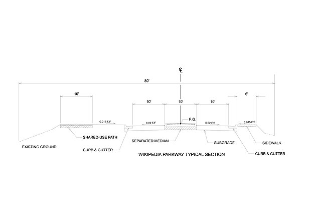
A typical cross-section drawing of a roadway.


