Planar transmission line
Videos
Page
Planar transmission lines are transmission lines with conductors, or in some cases dielectric (insulating) strips, that are flat, ribbon-shaped lines. They are used to interconnect components on printed circuits and integrated circuits working at microwave frequencies because the planar type fits in well with the manufacturing methods for these components. Transmission lines are more than simply interconnections. With simple interconnections, the propagation of the electromagnetic wave along the wire is fast enough to be considered instantaneous, and the voltages at each end of the wire can be considered identical. If the wire is longer than a large fraction of a wavelength, these assumptions are no longer true and transmission line theory must be used instead. With transmission lines, the geometry of the line is precisely controlled so that its electrical behaviour is highly predictable. At lower frequencies, these considerations are only necessary for the cables connecting different pieces of equipment, but at microwave frequencies the distance at which transmission line theory becomes necessary is measured in millimetres. Hence, transmission lines are needed within circuits.
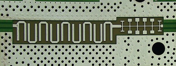
Printed circuit planar transmission lines used to create filters in a 20 GHz spectrum analyser. The structure on the left is called a hairpin filter and is an example of a band-pass filter. The structure on the right is a stub filter and is a low-pass filter. The perforated regions above and below are not transmission lines, but electromagnetic shielding for the circuit.

An RF power amplifier incorporating planar circuit structures. The amplifier on the left feeds its output into a set of planar transmission line filters in the centre. The third circuit block on the right is a circulator to protect the amplifier from accidental reflections of the power back from the antenna
Transmission line
Videos
Page
In electrical engineering, a transmission line is a specialized cable or other structure designed to conduct electromagnetic waves in a contained manner. The term applies when the conductors are long enough that the wave nature of the transmission must be taken into account. This applies especially to radio-frequency engineering because the short wavelengths mean that wave phenomena arise over very short distances. However, the theory of transmission lines was historically developed to explain phenomena on very long telegraph lines, especially submarine telegraph cables.
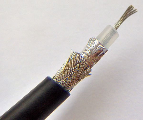
One of the most common types of transmission line, coaxial cable

A type of transmission line called a cage line, used for high power, low frequency applications. It functions similarly to a large coaxial cable. This example is the antenna feed line for a longwave radio transmitter in Poland, which operates at a frequency of 225 kHz and a power of 1200 kW.

A simple example of stepped transmission line consisting of three segments

Image: Polar Smith