Raw image format
Videos
Page
A camera raw image file contains unprocessed or minimally processed data from the image sensor of either a digital camera, a motion picture film scanner, or other image scanner. Raw files are so named because they are not yet processed, and contain large amounts of potentially redundant data. Normally, the image is processed by a raw converter, in a wide-gamut internal color space where precise adjustments can be made before conversion to a viewable file format such as JPEG or PNG for storage, printing, or further manipulation. There are dozens of raw formats in use by different manufacturers of digital image capture equipment.
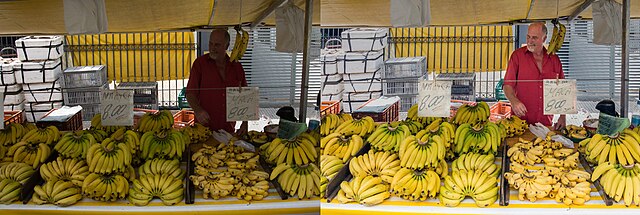
The raw file (left) before highlight and shadow details were recovered using the levels tool (right)
Motion picture film scanner
Videos
Page
A motion picture film scanner is a device used in digital filmmaking to scan original film for storage as high-resolution digital intermediate files.
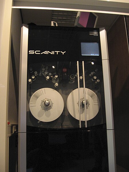
Film scanner at EYE Film Institute Netherlands, 2014

SDC-2000 Spirit DataCine Film Deck
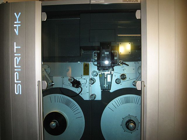
Spirit Datacine 4k with the doors closed
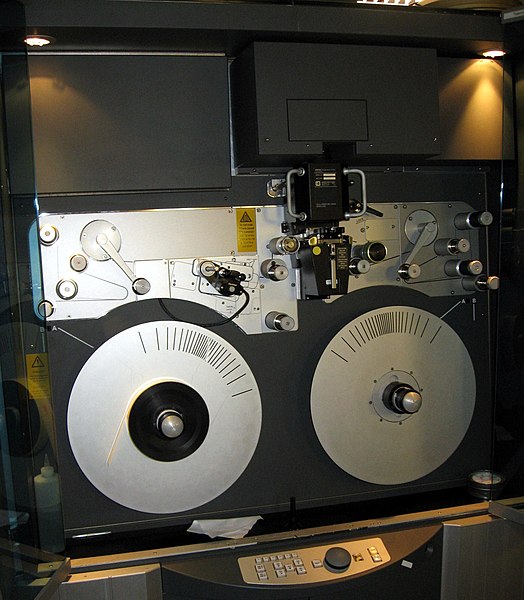
Spirit Datacine 4k with the doors open.jpg