AM broadcasting
Videos
Photos
AM broadcasting is radio broadcasting using amplitude modulation (AM) transmissions. It was the first method developed for making audio radio transmissions, and is still used worldwide, primarily for medium wave transmissions, but also on the longwave and shortwave radio bands.

Lee de Forest used an early vacuum-tube transmitter to broadcast returns for the Hughes-Wilson presidential election returns on November 7, 1916, over 2XG in New York City. Pictured is engineer Charles Logwood.

Nellie Melba making a broadcast over the Marconi Chelmsford Works radio station in England on 15 June 1920

Farmer listening to U.S. government weather and crop reports using a crystal radio in 1923. Public service government time, weather, and farm broadcasts were the first radio "broadcasts".

1938 Zenith Model 12-S vacuum-tube console radio, capable of picking up mediumwave and shortwave AM transmissions. "All Wave" receivers could also pick up the third AM band: longwave (LW).
Radio broadcasting
Videos
Photos
Radio broadcasting is the broadcasting of audio (sound), sometimes with related metadata, by radio waves to radio receivers belonging to a public audience. In terrestrial radio broadcasting the radio waves are broadcast by a land-based radio station, while in satellite radio the radio waves are broadcast by a satellite in Earth orbit. To receive the content the listener must have a broadcast radio receiver (radio). Stations are often affiliated with a radio network that provides content in a common radio format, either in broadcast syndication or simulcast, or both. Radio stations broadcast with several different types of modulation: AM radio stations transmit in AM, FM radio stations transmit in FM, which are older analog audio standards, while newer digital radio stations transmit in several digital audio standards: DAB, HD radio, DRM.
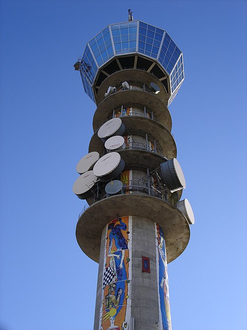
Broadcasting tower in Trondheim, Norway
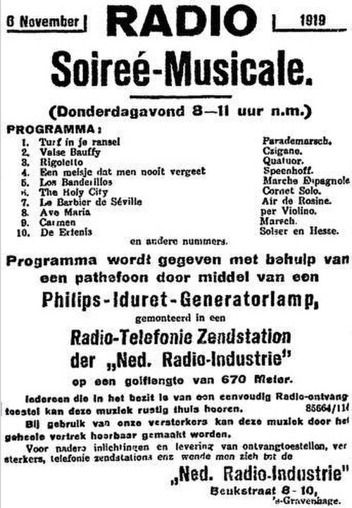
Advertisement placed on November 5, 1919, Nieuwe Rotterdamsche Courant announcing PCGG's debut broadcast scheduled for the next evening

Control room and radio studio of the Finnish broadcasting company Yleisradio (YLE) in the 1930s.

Use of a sound broadcasting station