The cavity magnetron is a high-power vacuum tube used in early radar systems and subsequently in microwave ovens and in linear particle accelerators. A cavity magnetron generates microwaves using the interaction of a stream of electrons with a magnetic field, while moving past a series of cavity resonators, which are small, open cavities in a metal block. Electrons pass by the cavities and cause microwaves to oscillate within, similar to the functioning of a whistle producing a tone when excited by an air stream blown past its opening. The resonant frequency of the arrangement is determined by the cavities' physical dimensions. Unlike other vacuum tubes, such as a klystron or a traveling-wave tube (TWT), the magnetron cannot function as an amplifier for increasing the intensity of an applied microwave signal; the magnetron serves solely as an electronic oscillator generating a microwave signal from direct current electricity supplied to the vacuum tube.

Magnetron with section removed to exhibit the cavities. The cathode in the center is not visible. The antenna emitting microwaves is at the left. The magnets producing a field parallel to the long axis of the device are not shown.
A similar magnetron with a different section removed. Central cathode is visible; antenna conducting microwaves at the top; magnets are not shown.
Obsolete 9 GHz magnetron tube and magnets from a Soviet aircraft radar. The tube is embraced between the poles of two horseshoe-shaped alnico magnets (top, bottom), which create a magnetic field along the axis of the tube. The microwaves are emitted from the waveguide aperture (top) which in use is attached to a waveguide conducting the microwaves to the radar antenna. Modern tubes use rare-earth magnets, electromagnets or ferrite magnets which are much less bulky.
Split-anode magnetron (c. 1935). (left) The bare tube, about 11 cm high. (right) Installed for use between the poles of a strong permanent magnet
A vacuum tube, electron tube, valve, or tube, is a device that controls electric current flow in a high vacuum between electrodes to which an electric potential difference has been applied.
Later thermionic vacuum tubes, mostly miniature style, some with top cap connections for higher voltages
Hot tubes in an audio power amplifier, emitting their distinctive red-orange glow
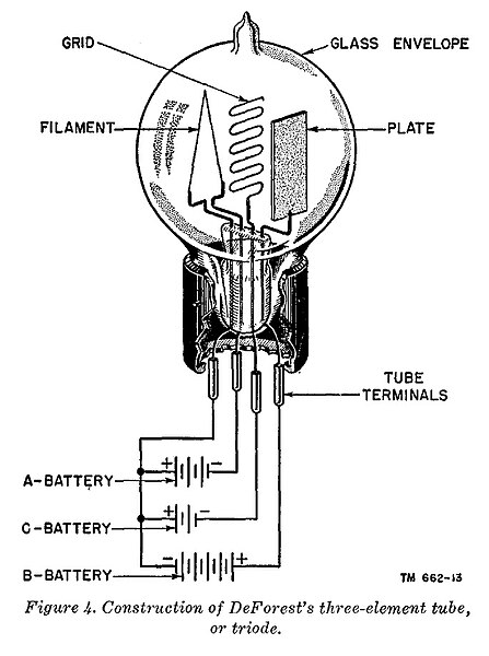
Illustration representing a primitive triode vacuum tube and the polarities of the typical DC operating potentials. Not shown are the impedances (resistors or inductors) that would be included in series with the C and B voltage sources.
Radio station signal generator with vacuum tubes


