Earth–ionosphere waveguide
The Earth–ionosphere waveguide is the phenomenon in which certain radio waves can propagate in the space between the ground and the boundary of the ionosphere.
Because the ionosphere contains charged particles, it can behave as a conductor. The earth operates as a ground plane, and the resulting cavity behaves as a large waveguide.
Figure 1. Geometry of ray propagation within the Earth–ionosphere waveguide. The ground wave and two sky waves are displayed
Figure 2. Real and virtual reflection height
Figure 3. Normalized vertical field strength Ez vs. distance ρ in magnitude (solid line, left ordinate) and phase (dashed line, right ordinate).
Figure 4. Magnitude of transfer functions of the zeroth mode and the first mode versus frequency at distances 1000, 3000, and 10000 km using day time conditions.
The ionosphere is the ionized part of the upper atmosphere of Earth, from about 48 km (30 mi) to 965 km (600 mi) above sea level, a region that includes the thermosphere and parts of the mesosphere and exosphere. The ionosphere is ionized by solar radiation. It plays an important role in atmospheric electricity and forms the inner edge of the magnetosphere. It has practical importance because, among other functions, it influences radio propagation to distant places on Earth. It also affects GPS signals that travel through this layer.
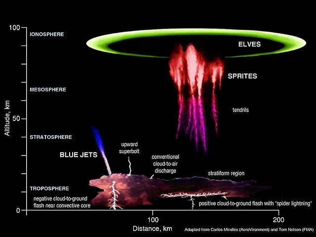
Lightning sprites.
Overview of ionosphere phenomena
Electric currents created in sunward ionosphere.