1.
Disk storage
–
Disk storage is a general category of storage mechanisms where data are recorded by various electronic, magnetic, optical, or mechanical changes to a surface layer of one or more rotating disks. A disk drive is a device implementing such a storage mechanism, notable types are the hard disk drive containing a non-removable disk, the floppy disk drive and its removable floppy disk, and various optical disc drives and associated optical disc media. Audio information was recorded by analog methods. Similarly the first video disc used a recording method. In the music industry, analog recording has mostly replaced by digital optical technology where the data are recorded in a digital format with optical information. The first commercial digital disk storage device was the IBM350 which shipped in 1956 as a part of the IBM305 RAMAC computing system, the random-access, low-density storage of disks was developed to complement the already used sequential-access, high-density storage provided by tape drives using magnetic tape. Disk storage is now used in computer storage and consumer electronic storage, e. g. audio CDs and video discs. Digital disk drives are block storage devices, each disk is divided into logical blocks. Blocks are addressed using their logical block addresses, read from or writing to disk happens at the granularity of blocks. Originally the disk capacity was low and has been improved in one of several ways. Improvements in mechanical design and manufacture allowed smaller and more precise heads, advancements in data compression methods permitted more information to be stored in each of the individual sectors. The drive stores data onto cylinders, heads, and sectors, the sectors unit is the smallest size of data to be stored in a hard disk drive and each file will have many sectors units assigned to it. The smallest entity in a CD is called a frame, which consists of 33 bytes, the other nine bytes consist of eight CIRC error-correction bytes and one subcode byte used for control and display. The information is sent from the processor to the BIOS into a chip controlling the data transfer. This is then sent out to the drive via a multi-wire connector. Once the data are received onto the board of the drive. The data are passed to a chip on the circuit board that controls the access to the drive. The drive is divided into sectors of data stored onto one of the sides of one of the internal disks, an HDD with two disks internally will typically store data on all four surfaces
2.
Magnetic storage
–
Magnetic storage or magnetic recording is the storage of data on a magnetised medium. Magnetic storage uses different patterns of magnetisation in a material to store data and is a form of non-volatile memory. The information is accessed using one or more read/write heads, as of 2017, magnetic storage media, primarily hard disks, are widely used to store computer data as well as audio and video signals. In the field of computing, the magnetic storage is preferred and in the field of audio and video production. The distinction is less technical and more a matter of preference, other examples of magnetic storage media include floppy disks, magnetic recording tape, and magnetic stripes on credit cards. Magnetic storage in the form of wire recording—audio recording on a wire—was publicized by Oberlin Smith in the Sept 8,1888 issue of the Electrical World. Smith had previously filed a patent in September,1878 but found no opportunity to pursue the idea as his business was machine tools, the first publicly demonstrated magnetic recorder was invented by Valdemar Poulsen in 1898. Poulsens device recorded a signal on a wire wrapped around a drum, in 1928, Fritz Pfleumer developed the first magnetic tape recorder. Early magnetic storage devices were designed to record analog audio signals, computers and now most audio and video magnetic storage devices record digital data. In old computers, magnetic storage was used for primary storage in a form of magnetic drum, or core memory, core rope memory, thin film memory. Unlike modern computers, magnetic tape was often used for secondary storage. Information is written to and read from the medium as it moves past devices called read-and-write heads that operate very close over the magnetic surface. The read-and-write head is used to detect and modify the magnetisation of the material immediately under it, there are two magnetic polarities, each of which is used to represent either 0 or 1. The magnetic surface is divided into many small sub-micrometer-sized magnetic regions, referred to as magnetic domains. Due to the nature of the magnetic material each of these magnetic regions is composed of a few hundred magnetic grains. Magnetic grains are typically 10 nm in size and each form a single magnetic domain. Each magnetic region in total forms a magnetic dipole which generates a magnetic field, for reliable storage of data, the recording material needs to resist self-demagnetisation, which occurs when the magnetic domains repel each other. Magnetic domains written too densely together to a weakly magnetisable material will degrade over time due to rotation of the moment one or more domains to cancel out these forces
3.
USB
–
It is currently developed by the USB Implementers Forum. USB was designed to standardize the connection of peripherals to personal computers. It has become commonplace on other devices, such as smartphones, PDAs, USB has effectively replaced a variety of earlier interfaces, such as serial ports and parallel ports, as well as separate power chargers for portable devices. Also, there are 5 modes of USB data transfer, in order of increasing bandwidth, Low Speed, Full Speed, High Speed, SuperSpeed, USB devices have some choice of implemented modes, and USB version is not a reliable statement of implemented modes. Modes are identified by their names and icons, and the specifications suggests that plugs, unlike other data buses, USB connections are directed, with both upstream and downstream ports emanating from a single host. This applies to power, with only downstream facing ports providing power. Thus, USB cables have different ends, A and B, therefore, in general, each different format requires four different connectors, a plug and receptacle for each of the A and B ends. USB cables have the plugs, and the corresponding receptacles are on the computers or electronic devices, in common practice, the A end is usually the standard format, and the B side varies over standard, mini, and micro. The mini and micro formats also provide for USB On-The-Go with a hermaphroditic AB receptacle, the micro format is the most durable from the point of view of designed insertion lifetime. The standard and mini connectors have a lifetime of 1,500 insertion-removal cycles. Likewise, the component of the retention mechanism, parts that provide required gripping force, were also moved into plugs on the cable side. A group of seven companies began the development of USB in 1994, Compaq, DEC, IBM, Intel, Microsoft, NEC, a team including Ajay Bhatt worked on the standard at Intel, the first integrated circuits supporting USB were produced by Intel in 1995. The original USB1.0 specification, which was introduced in January 1996, Microsoft Windows 95, OSR2.1 provided OEM support for the devices. The first widely used version of USB was 1.1, the 12 Mbit/s data rate was intended for higher-speed devices such as disk drives, and the lower 1.5 Mbit/s rate for low data rate devices such as joysticks. Apple Inc. s iMac was the first mainstream product with USB, following Apples design decision to remove all legacy ports from the iMac, many PC manufacturers began building legacy-free PCs, which led to the broader PC market using USB as a standard. The USB2.0 specification was released in April 2000 and was ratified by the USB Implementers Forum at the end of 2001.1 specification, the USB3.0 specification was published on 12 November 2008. Its main goals were to increase the transfer rate, decrease power consumption, increase power output. USB3.0 includes a new, higher speed bus called SuperSpeed in parallel with the USB2.0 bus, for this reason, the new version is also called SuperSpeed
4.
USB flash drive
–
USB flash drives are typically removable and rewritable, and physically much smaller than an optical disc. Most weigh less than 30 grams, since first appearing on the market in late 2000, as with virtually all computer memory devices, storage capacities have risen while prices have dropped. As of March 2016, flash drives with anywhere from 8 to 256 GB are frequently sold, storage capacities as large as 2 TB are planned, with steady improvements in size and price per capacity expected. Some allow up to 100,000 write/erase cycles, depending on the type of memory chip used. USB flash drives are used for the same purposes for which floppy disks or CDs were once used, i. e. for storage, data back-up. They are smaller, faster, have thousands of times more capacity, additionally, they are immune to electromagnetic interference, and are unharmed by surface scratches.44 MB3. 5-inch floppy disk. The USB connector may be protected by a cap or by retracting into the body of the drive. Most flash drives use a standard type-A USB connection allowing connection with a port on a personal computer, USB flash drives draw power from the computer via the USB connection. Some devices combine the functionality of a media player with USB flash storage. Pua Khein-Seng from Malaysia is considered by many to be the Father of Pen Drive and he is notable for incorporating the worlds first single chip USB flash controller. Pua hails from Sekinchan, Selangor, Malaysia, pua founded Phison Electronics based in Taiwan with four other partners and is believed to have produced the worlds first USB flash drive with system-on-chip technology. Competing claims have made by Singaporean company Trek Technology and Chinese company Netac Technology, Both Trek Technology. Trek won a Singaporean suit, but a court in the United Kingdom revoked one of Treks UK patents, Trek Technology and IBM began selling the first USB flash drives commercially in 2000. IBMs USB flash drive became available on December 15,2000, in 2000, Lexar introduced a Compact Flash card with a USB connection, and a companion card read/writer and USB cable that eliminated the need for a USB hub. That is considerably slower than what a hard drive or solid-state drive can achieve when connected via the SATA interface. Transfer rates may be given in megabytes per second, megabits per second, or in optical drive multipliers such as 180X.1, which is limited to 12 Mbit/s with accounted overhead. The effective transfer rate of a device is significantly affected by the access pattern, for example. Like USB2.0 before it, USB3.0 dramatically improved data rates compared to its predecessor
5.
Memory card
–
A memory card, flash card or memory cartridge is an electronic flash memory data storage device used for storing digital information. PC Cards were the first commercial memory card formats to come out, since 1994, a number of memory card formats smaller than the PC Card arrived, the first one was CompactFlash later SmartMedia and Miniature Card. The desire for smaller cards for cell-phones, PDAs, and compact digital cameras drove a trend that left the previous generation of compact cards looking big, in digital cameras SmartMedia and CompactFlash had been very successful. In 2001, SM alone captured 50% of the camera market. By 2005 however, SD/MMC had nearly taken over SmartMedias spot, though not to the level and with stiff competition coming from Memory Stick variants. In industrial and embedded fields, even the venerable PC card memory cards still manage to maintain a niche, while in mobile phones and PDAs, since 2010, new products of Sony and Olympus have been offered with an additional SD-Card slot. Effectively the format war has turned in SD-Cards favor, PCMCIA ATA Type I Card PCMCIA Type II, Type III cards CompactFlash Card, CompactFlash High-Speed CompactFlash Type II, CF+, CF3. MU-Flash C-Flash SIM card Smart card UFC FISH Universal Transportable Memory Card Standard Intelligent Stick SxS memory card, SxS complies to the ExpressCard industry standard. Nexflash Winbond Serial Flash Module cards, size range 1 mb,2 mb and 4 mb, many older video game consoles used memory cards to hold saved game data. Cartridge-based systems primarily used battery-backed volatile RAM within each individual cartridge to hold saves for that game, cartridges without this RAM may have used a password system, or wouldnt save progress at all. The Neo Geo AES, released in 1990 by SNK, was the first video game console able to use a memory card, AES memory cards were also compatible with Neo-Geo MVS arcade cabinets, allowing players to migrate saves between home and arcade systems and vice versa. Memory cards became commonplace when home consoles moved to read-only optical discs for storing the game program, until the sixth generation of video game consoles, memory cards were based on proprietary formats, later systems have used established industry hardware formats for memory cards, such as FAT32. Comparison of memory cards Hot swapping
6.
Hard disk drive
–
The platters are paired with magnetic heads, usually arranged on a moving actuator arm, which read and write data to the platter surfaces. Data is accessed in a manner, meaning that individual blocks of data can be stored or retrieved in any order. HDDs are a type of storage, retaining stored data even when powered off. Introduced by IBM in 1956, HDDs became the dominant secondary storage device for computers by the early 1960s. Continuously improved, HDDs have maintained this position into the era of servers. More than 200 companies have produced HDDs historically, though after extensive industry consolidation most current units are manufactured by Seagate, Toshiba, as of 2016, HDD production is growing, although unit shipments and sales revenues are declining. While SSDs have higher cost per bit, SSDs are replacing HDDs where speed, power consumption, small size, the primary characteristics of an HDD are its capacity and performance. Capacity is specified in unit prefixes corresponding to powers of 1000, the two most common form factors for modern HDDs are 3. 5-inch, for desktop computers, and 2. 5-inch, primarily for laptops. HDDs are connected to systems by standard interface cables such as PATA, SATA, Hard disk drives were introduced in 1956, as data storage for an IBM real-time transaction processing computer and were developed for use with general-purpose mainframe and minicomputers. The first IBM drive, the 350 RAMAC in 1956, was approximately the size of two medium-sized refrigerators and stored five million six-bit characters on a stack of 50 disks. In 1962 the IBM350 RAMAC disk storage unit was superseded by the IBM1301 disk storage unit, cylinder-mode read/write operations were supported, and the heads flew about 250 micro-inches above the platter surface. Motion of the head array depended upon a binary system of hydraulic actuators which assured repeatable positioning. The 1301 cabinet was about the size of three home refrigerators placed side by side, storing the equivalent of about 21 million eight-bit bytes, access time was about a quarter of a second. Also in 1962, IBM introduced the model 1311 disk drive, users could buy additional packs and interchange them as needed, much like reels of magnetic tape. Later models of removable pack drives, from IBM and others, became the norm in most computer installations, non-removable HDDs were called fixed disk drives. Some high-performance HDDs were manufactured with one head per track so that no time was lost physically moving the heads to a track, known as fixed-head or head-per-track disk drives they were very expensive and are no longer in production. In 1973, IBM introduced a new type of HDD code-named Winchester and its primary distinguishing feature was that the disk heads were not withdrawn completely from the stack of disk platters when the drive was powered down. Instead, the heads were allowed to land on an area of the disk surface upon spin-down
7.
Optical disc
–
The encoding material sits atop a thicker substrate which makes up the bulk of the disc and forms a dust defocusing layer. The encoding pattern follows a continuous, spiral path covering the disc surface. Most optical discs exhibit a characteristic iridescence as a result of the diffraction grating formed by its grooves and this side of the disc contains the actual data and is typically coated with a transparent material, usually lacquer. The reverse side of a disc usually has a printed label, sometimes made of paper. Optical discs are usually between 7.6 and 30 cm in diameter, with 12 cm being the most common size, a typical disc is about 1.2 mm thick, while the track pitch ranges from 1.6 µm to 320 nm. An optical disc is designed to support one of three recording types, read-only, recordable, or re-recordable, write-once optical discs commonly have an organic dye recording layer between the substrate and the reflective layer. Rewritable discs typically contain an alloy recording layer composed of a phase change material, most often AgInSbTe, an alloy of silver, indium, antimony, Optical discs are most commonly used for storing music, video, or data and programs for personal computers. The Optical Storage Technology Association promotes standardized optical storage formats, although optical discs are more durable than earlier audio-visual and data storage formats, they are susceptible to environmental and daily-use damage. Libraries and archives enact optical media preservation procedures to ensure continued usability in the optical disc drive or corresponding disc player. For computer data backup and physical data transfer, optical discs such as CDs and DVDs are gradually being replaced with faster, smaller solid-state devices and this trend is expected to continue as USB flash drives continue to increase in capacity and drop in price. Additionally, music purchased or shared over the Internet has significantly reduced the number of audio CDs sold annually. The first recorded use of an optical disc was in the 1884 when Alexander Graham Bell, Chichester Bell. An early optical disc system existed in 1935, named Lichttonorgel, an early analog optical disc used for video recording was invented by David Paul Gregg in 1958 and patented in the US in 1961 and 1969. This form of optical disc was an early form of the DVD. It is of special interest that U. S, patent 4,893,297, filed 1989, issued 1990, generated royalty income for Pioneer Corporations DVA until 2007 —then encompassing the CD, DVD, and Blu-ray systems. In the early 1960s, the Music Corporation of America bought Greggs patents and his company, american inventor James T. Russell has been credited with inventing the first system to record a digital signal on an optical transparent foil which is lit from behind by a high-power halogen lamp. Russells patent application was first filed in 1966 and he was granted a patent in 1970, following litigation, Sony and Philips licensed Russells patents in the 1980s. Both Greggs and Russells disc are floppy media read in transparent mode, in the Netherlands in 1969, Philips Research physicist, Pieter Kramer invented an optical videodisc in reflective mode with a protective layer read by a focused laser beam U. S
8.
ROM cartridge
–
ROM cartridges can be used to load software such as video games or other application programs. The cartridge slot could also be used for additions, for example speech synthesis. Some cartridges had battery-backed static random-access memory, allowing a user to save data such as game progress or scores between uses, an advantage for the manufacturer was the relative security of the software in cartridge form, which was difficult for end users to replicate. However, cartridges were expensive to manufacture compared to making a floppy disk or CD-ROM, as disk drives became more common and software expanded beyond the practical limits of ROM size, cartridge slots disappeared from later game consoles and personal computers. Cartridges are still used today with handheld gaming consoles such as the Nintendo DS, Nintendo 3DS, due to its widespread usage for video gaming, ROM cartridges were often colloquially referred to as a game cartridge. ROM cartridges were popularized by early home computers which featured a special bus port for the insertion of cartridges containing software in ROM. Notable computers using cartridges in addition to magnetic media were the Commodore VIC-20 and 64, MSX standard, the Atari 8-bit family, the Texas Instruments TI-99/4A, some arcade system boards, such as Capcoms CP System and SNKs Neo Geo, also used ROM cartridges. The modern take on game cartridges was invented by Jerry Lawson as part of the Fairchild Channel F home console in 1976, the cartridge approach gained more popularity with the Atari 2600 released the following year. From the late 1970s to mid-1990s, the majority of video game systems were cartridge-based. As compact disc technology came to be used widely for data storage, Nintendo remained the lone hold-out, using cartridges for their Nintendo 64 system, the company did not transition to optical media until 2001s GameCube. SNK still released games on the cartridge based Neo Geo until 2004, ROM cartridges can not only carry software, but additional hardware expansion as well. Examples include the Super FX coprocessor chip in some Super NES game paks, micro Machines 2 on the Genesis/Mega Drive used a custom J-Cart cartridge design by Codemasters which incorporated two additional gamepad ports. This allowed players to have up to four gamepads connected to the console without the need for an additional multi-controller adapter, the ROM cartridge slot principle continues in various mobile devices, thanks to the development of high density low-cost flash memory. For example, a GPS navigation device might allow user updates of maps by inserting a memory chip into an expansion slot. An E-book reader can store the text of several books on a flash chip. Personal computers may allow the user to boot and install a system off a USB flash drive instead of CD ROM or floppy disks. Digital cameras with flash drive slots allow users to exchange cards when full. Storing software on ROM cartridges has a number of advantages over other methods of storage like floppy disks, software run directly from ROM typically uses less RAM, leaving memory free for other processes
9.
Computer network
–
A computer network or data network is a telecommunications network which allows nodes to share resources. In computer networks, networked computing devices exchange data with other using a data link. The connections between nodes are established using either cable media or wireless media, the best-known computer network is the Internet. Network computer devices that originate, route and terminate the data are called network nodes, nodes can include hosts such as personal computers, phones, servers as well as networking hardware. Two such devices can be said to be networked together when one device is able to exchange information with the other device, Computer networks differ in the transmission medium used to carry their signals, communications protocols to organize network traffic, the networks size, topology and organizational intent. In most cases, application-specific communications protocols are layered over other more general communications protocols and this formidable collection of information technology requires skilled network management to keep it all running reliably. The chronology of significant computer-network developments includes, In the late 1950s, in 1960, the commercial airline reservation system semi-automatic business research environment went online with two connected mainframes. Licklider developed a group he called the Intergalactic Computer Network. In 1964, researchers at Dartmouth College developed the Dartmouth Time Sharing System for distributed users of computer systems. The same year, at Massachusetts Institute of Technology, a group supported by General Electric and Bell Labs used a computer to route. Throughout the 1960s, Leonard Kleinrock, Paul Baran, and Donald Davies independently developed network systems that used packets to transfer information between computers over a network, in 1965, Thomas Marill and Lawrence G. Roberts created the first wide area network. This was an precursor to the ARPANET, of which Roberts became program manager. Also in 1965, Western Electric introduced the first widely used telephone switch that implemented true computer control, in 1972, commercial services using X.25 were deployed, and later used as an underlying infrastructure for expanding TCP/IP networks. In July 1976, Robert Metcalfe and David Boggs published their paper Ethernet, Distributed Packet Switching for Local Computer Networks, in 1979, Robert Metcalfe pursued making Ethernet an open standard. In 1976, John Murphy of Datapoint Corporation created ARCNET, a network first used to share storage devices. In 1995, the transmission speed capacity for Ethernet increased from 10 Mbit/s to 100 Mbit/s, by 1998, Ethernet supported transmission speeds of a Gigabit. Subsequently, higher speeds of up to 100 Gbit/s were added, the ability of Ethernet to scale easily is a contributing factor to its continued use. Providing access to information on shared storage devices is an important feature of many networks, a network allows sharing of files, data, and other types of information giving authorized users the ability to access information stored on other computers on the network
10.
History of the floppy disk
–
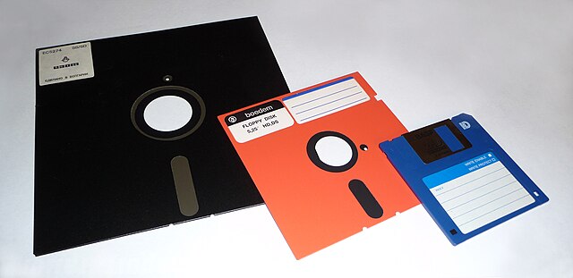
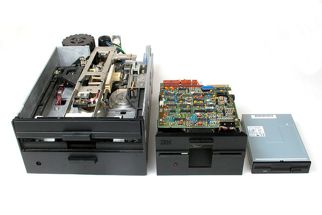
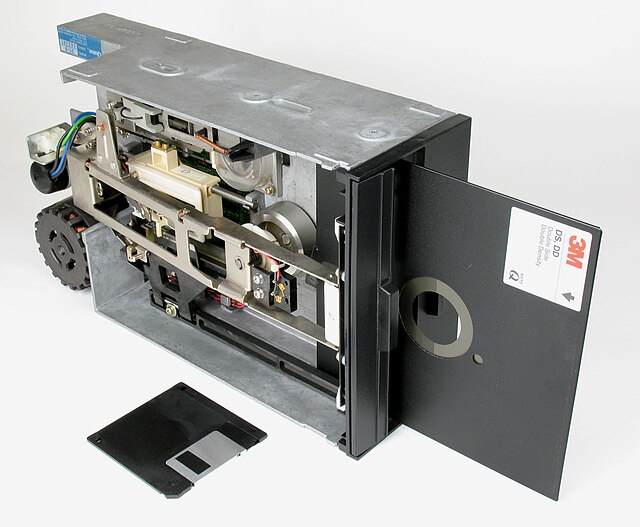
Work on the drive for what became the media of the worlds first floppy disk drive began in 1967 at a San Jose IBM facility. First introduced into the market as 8-inch floppy disks in 1972, they were followed by 5¼-inch disks in 1976, a number of varient sizes with limited market success were also available. Low-cost floppy drives became indispensable for word processors and PCs, floppy disks remained a popular portable digital-storage medium for nearly 40 years. Sizes ranged from 8 inches in the first commercialized floppy disk to the popular-in-its-day 5¼-inch minifloppy to the 3½-inch floppy disks still available today. There was a time in the late 1980s and early 1990s when some software was shipped with both 5¼-inch and 3½-inch floppy disks or was offered in a choice of either, e. g. MS-DOS6. IBM also wanted inexpensive media that could be sent out to customers with software updates, IBM Direct Access Storage Product Manager, Alan Shugart, assigned the job to David L. Noble, who tried to develop a new-style tape for the purpose, but without success. Nobles team developed a read-only, 8-inch-diameter flexible diskette they called the memory disk, the original disk was bare, but dirt became a serious problem so they enclosed it in a plastic envelope lined with fabric that would remove dust particles. IBM introduced the diskette commercially in 1971, internally IBM used another device, code named Mackerel, to write boot disks for distribution to the field. Alan Shugart left IBM and moved to Memorex where his team shipped the Memorex 650 in 1972, the 650 had a data capacity of 175 kB, with 50 tracks,8 sectors per track, and 448 bytes per sector. The Memorex disk was hard-sectored, that is, it contained 8 sector holes at the outer diameter to synchronize the beginning of each data sector, a significant feature of IBMs read/write disk media was the use of a Teflon-lubricated fabric liner to lengthen media life. In 1976, media supplier Information Terminals Corporation enhanced resilience further by adding a Teflon coating to the disk itself. The new system used a different recording format that stored up to 250¼ kB on the same disks, drives supporting this format were offered by a number of manufacturers and soon became common for moving smaller amounts of data. This disk format became known as the Single Sided Single Density or SSSD format and it was designed to hold just as much data as one box of 2000 punch cards. The disk was divided into 77 tracks of 26 sectors, each holding 128 bytes, the first microcomputer operating system, CP/M, originally shipped on 8-inch disks. However, the drives were expensive, typically costing more than the computer they were attached to in early days. Also in 1973, Shugart founded Shugart Associates which went on to become the dominant manufacturer of 8-inch floppy disk drives and its SA800 became the industry standard for form factor and interface. In 1976, IBM introduced the 500 KB Double Sided Single Density format, other 8-inch floppy disk formats such as the Burroughs 1 MB unit failed to achieve any market presence. He argued for a $100 drive, the same price point was echoed during monthly visits of Steve Jobs to the Shugart labs, looking for an affordable alternative to the cassette tape drives then being used on the Apple II
11.
Computer memory
–
In computing, memory refers to the computer hardware devices involved to store information for immediate use in a computer, it is synonymous with the term primary storage. Computer memory operates at a speed, for example random-access memory, as a distinction from storage that provides slow-to-access program and data storage. If needed, contents of the memory can be transferred to secondary storage. An archaic synonym for memory is store, there are two main kinds of semiconductor memory, volatile and non-volatile. Examples of non-volatile memory are flash memory and ROM, PROM, EPROM and EEPROM memory, most semiconductor memory is organized into memory cells or bistable flip-flops, each storing one bit. Flash memory organization includes both one bit per cell and multiple bits per cell. The memory cells are grouped into words of fixed word length, each word can be accessed by a binary address of N bit, making it possible to store 2 raised by N words in the memory. This implies that processor registers normally are not considered as memory, since they only store one word, typical secondary storage devices are hard disk drives and solid-state drives. In the early 1940s, memory technology oftenly permit a capacity of a few bytes, the next significant advance in computer memory came with acoustic delay line memory, developed by J. Presper Eckert in the early 1940s. Delay line memory would be limited to a capacity of up to a few hundred thousand bits to remain efficient, two alternatives to the delay line, the Williams tube and Selectron tube, originated in 1946, both using electron beams in glass tubes as means of storage. Using cathode ray tubes, Fred Williams would invent the Williams tube, the Williams tube would prove more capacious than the Selectron tube and less expensive. The Williams tube would prove to be frustratingly sensitive to environmental disturbances. Efforts began in the late 1940s to find non-volatile memory, jay Forrester, Jan A. Rajchman and An Wang developed magnetic core memory, which allowed for recall of memory after power loss. Magnetic core memory would become the dominant form of memory until the development of transistor-based memory in the late 1960s, developments in technology and economies of scale have made possible so-called Very Large Memory computers. The term memory when used with reference to computers generally refers to Random Access Memory or RAM, volatile memory is computer memory that requires power to maintain the stored information. Most modern semiconductor volatile memory is either static RAM or dynamic RAM, SRAM retains its contents as long as the power is connected and is easy for interfacing, but uses six transistors per bit. SRAM is not worthwhile for desktop system memory, where DRAM dominates, SRAM is commonplace in small embedded systems, which might only need tens of kilobytes or less. Forthcoming volatile memory technologies that aim at replacing or competing with SRAM and DRAM include Z-RAM and A-RAM, non-volatile memory is computer memory that can retain the stored information even when not powered
12.
Random-access memory
–
Random-access memory is a form of computer data storage which stores frequently used program instructions to increase the general speed of a system. A random-access memory device allows data items to be read or written in almost the same amount of time irrespective of the location of data inside the memory. RAM contains multiplexing and demultiplexing circuitry, to connect the lines to the addressed storage for reading or writing the entry. Usually more than one bit of storage is accessed by the same address, in todays technology, random-access memory takes the form of integrated circuits. RAM is normally associated with types of memory, where stored information is lost if power is removed. Other types of non-volatile memories exist that allow access for read operations. These include most types of ROM and a type of memory called NOR-Flash. Integrated-circuit RAM chips came into the market in the early 1970s, with the first commercially available DRAM chip, early computers used relays, mechanical counters or delay lines for main memory functions. Ultrasonic delay lines could only reproduce data in the order it was written, drum memory could be expanded at relatively low cost but efficient retrieval of memory items required knowledge of the physical layout of the drum to optimize speed. Latches built out of vacuum tube triodes, and later, out of transistors, were used for smaller and faster memories such as registers. Such registers were relatively large and too costly to use for large amounts of data, the first practical form of random-access memory was the Williams tube starting in 1947. It stored data as electrically charged spots on the face of a cathode ray tube, since the electron beam of the CRT could read and write the spots on the tube in any order, memory was random access. The capacity of the Williams tube was a few hundred to around a thousand bits, but it was smaller, faster. In fact, rather than the Williams tube memory being designed for the SSEM, magnetic-core memory was invented in 1947 and developed up until the mid-1970s. It became a form of random-access memory, relying on an array of magnetized rings. By changing the sense of each rings magnetization, data could be stored with one bit stored per ring, since every ring had a combination of address wires to select and read or write it, access to any memory location in any sequence was possible. Magnetic core memory was the form of memory system until displaced by solid-state memory in integrated circuits. Data was stored in the capacitance of each transistor, and had to be periodically refreshed every few milliseconds before the charge could leak away
13.
Dynamic random-access memory
–
Dynamic random-access memory is a type of random-access memory that stores each bit of data in a separate capacitor within an integrated circuit. The capacitor can be charged or discharged, these two states are taken to represent the two values of a bit, conventionally called 0 and 1. Since even nonconducting transistors always leak a small amount, the capacitors will slowly discharge, because of this refresh requirement, it is a dynamic memory as opposed to static random-access memory and other static types of memory. Unlike flash memory, DRAM is volatile memory, since it loses its data quickly when power is removed, however, DRAM does exhibit limited data remanence. DRAM is widely used in digital electronics where low-cost and high-capacity memory is required, one of the largest applications for DRAM is the main memory in modern computers, and as the main memories of components used in these computers such as graphics cards. In contrast, SRAM, which is faster and more expensive than DRAM, is used where speed is of greater concern than cost. The advantage of DRAM is its simplicity, only one transistor. This allows DRAM to reach high densities. The transistors and capacitors used are small, billions can fit on a single memory chip. Due to the nature of its memory cells, DRAM consumes relatively large amounts of power. The cryptanalytic machine code-named Aquarius used at Bletchley Park during World War II incorporated a dynamic memory. Paper tape was read and the characters on it were remembered in a dynamic store, the store used a large bank of capacitors, which were either charged or not, a charged capacitor representing cross and an uncharged capacitor dot. Since the charge gradually leaked away, a pulse was applied to top up those still charged. In 1964, Arnold Farber and Eugene Schlig, working for IBM, created a hard-wired memory cell, using a transistor gate and they replaced the latch with two transistors and two resistors, a configuration that became known as the Farber-Schlig cell. In 1965, Benjamin Agusta and his team at IBM created a 16-bit silicon memory chip based on the Farber-Schlig cell, with 80 transistors,64 resistors, in 1966, DRAM was invented by Dr. Robert Dennard at the IBM Thomas J. Watson Research Center. He was granted U. S. patent number 3,387,286 in 1968, capacitors had been used for earlier memory schemes such as the drum of the Atanasoff–Berry Computer, the Williams tube and the Selectron tube. The Toshiba Toscal BC-1411 electronic calculator, which was introduced in November 1966, the first DRAM was introduced in 1969 by Advanced Memory system, Inc of Sunnyvale, CA </ref>. This 1000 bit chip was sold to Honeywell, Raytheon, Wang Computer among others, in 1969 Honeywell asked Intel to make a DRAM using a three-transistor cell that they had developed
14.
Static random-access memory
–
Static random-access memory is a type of semiconductor memory that uses bistable latching circuitry to store each bit. SRAM exhibits data remanence, but it is volatile in the conventional sense that data is eventually lost when the memory is not powered. The term static differentiates SRAM from DRAM which must be periodically refreshed, SRAM is faster and more expensive than DRAM, it is typically used for CPU cache while DRAM is used for a computers main memory. Several techniques have been proposed to power consumption of SRAM-based memory structures. Some amount is also embedded in all modern appliances, toys. Several megabytes may be used in products such as digital cameras, cell phones, synthesizers. SRAM in its form is sometimes used for realtime digital signal processing circuits. LCD screens and printers also normally employ static RAM to hold the image displayed, static RAM was used for the main memory of some early personal computers such as the ZX80, TRS-80 Model 100 and Commodore VIC-20. Hobbyists, specifically homebuilt processor enthusiasts, often prefer SRAM due to the ease of interfacing and it is much easier to work with than DRAM as there are no refresh cycles and the address and data buses are directly accessible rather than multiplexed. In addition to buses and power connections, SRAM usually requires only three controls, Chip Enable, Write Enable and Output Enable, in synchronous SRAM, Clock is also included. Non-volatile SRAMs, or nvSRAMs, have standard SRAM functionality, but they save the data when the supply is lost. NvSRAMs are used in a range of situations – networking, aerospace, and medical, among many others – where the preservation of data is critical. Address, data in and other signals are associated with the clock signals In 1990s. Nowadays, synchronous SRAM is rather employed similarly like Synchronous DRAM – DDR SDRAM memory is used than asynchronous DRAM. Synchronous memory interface is much faster as access time can be reduced by employing pipeline architecture. Furthermore, as DRAM is much cheaper than SRAM, SRAM is often replaced by DRAM, SRAM memory is however much faster for random access. Therefore, SRAM memory is used for CPU cache, small on-chip memory. Zero bus turnaround – the turnaround is the number of cycles it takes to change access to the SRAM from write to read
15.
Williams tube
–
It was the first random-access digital storage device, and was used successfully in several early computers. Williams and Kilburn applied for British patents on December 11,1946, and October 2,1947, followed by US patent applications on December 10,1947, the Williams tube depends on an effect called secondary emission that occurs on cathode ray tubes. They travel a distance before being attracted back to the surface. The resulting charge well remains on the surface of the tube for a fraction of a second while the flow back to their original locations. The lifetime depends on the resistance of the phosphor and the size of the well. The process of creating the charge well is used as the operation in a computer memory, storing a single binary digit. A collection of dots or spaces, often one horizontal row on the display, there is a relationship between the size and spacing of the dots and their lifetime, as well as the ability to reject crosstalk with adjacent dots. This produces an upper limit on the density, and each Williams tube could typically store about 1024–2560 bits of data. Because the electron beam is essentially inertia free and can be moved anywhere on the display, reading the memory took place via a secondary effect caused by the writing operation. During the short period when the write takes place, the redistribution of charges in the phosphor creates a current that induces voltage in any nearby conductors. This is read by placing a metal sheet just in front of the display side of the CRT. During a read operation, the writes to the selected bit locations on the display. Those locations that were written to are already depleted of electrons, so no current flows. This allows the computer to determine there was a 1 in that location, if the location had not been written to previously, the write process will create a well and a pulse will be read on the plate, indicating a 0. In some systems this was accomplished using an electron gun inside the CRT that could write to one location while the other was reading the next. Since the display would fade over time, the display had to be periodically refreshed using the same basic method. However, as the data is read and then immediately written and this refresh operation is similar to the memory refresh cycles of DRAM in modern systems. Since the refresh process caused the same pattern to reappear on the display
16.
Delay line memory
–
Delay line memory is a form of computer memory, now obsolete, that was used on some of the earliest digital computers. Like many modern forms of computer memory, delay line memory was a refreshable memory. Analog delay line technology had been used since the 1920s to delay the propagation of analog signals, when a delay line is used as a memory device, an amplifier and a pulse shaper are connected between the output of the delay line and the input. The memory capacity is determined by dividing the time taken to transmit one bit into the time it takes for data to circulate through the delay line, early delay-line memory systems had capacities of a few thousand bits, with recirculation times measured in microseconds. To read or write a particular bit stored in such a memory, the delay to read or write any particular bit is no longer than the recirculation time. Use of a line for a computer memory was invented by J. Presper Eckert in the mid-1940s for use in computers such as the EDVAC. Eckert and John Mauchly applied for a patent for a delay line memory system on October 31,1947, the basic concept of the delay line originated with World War II radar research, as a system to reduce clutter from reflections from the ground and other fixed objects. A radar system consists principally of an antenna, a transmitter, a receiver, the antenna is connected to the transmitter, which sends out a brief pulse of radio energy before being disconnected again. The antenna is connected to the receiver, which amplifies any reflected signals. Objects farther from the return echos later in time than those located closer to the radar. Non-moving objects at a distance from the antenna always return a signal after the same delay. This would appear as a spot on the display, making detection of other targets in the area more difficult. Early radars simply aimed their beams away from the ground in order to avoid the majority of this clutter, to filter these returns out, two pulses were compared, and returns with common timing are removed. To do this, the signal sent from the receiver to the display was split in two, with one leading directly to the display, and the second leading to a delay unit. One of the signals was then inverted, typically the one from the delay, any signal that was at the same location was nullified by the inverted signal from a previous pulse, leaving only the moving objects on the display. Several different types of systems were invented for this purpose. MIT experimented with a number of systems including glass, quartz, steel, the Japanese deployed a system consisting of a quartz element with a powdered glass coating that reduced surface waves that interfered with proper reception. The United States Naval Research Laboratory used steel rods wrapped into a helix, raytheon used a magnesium alloy originally developed for making bells
17.
Selectron tube
–
The Selectron was an early form of digital computer memory developed by Jan A. Rajchman and his group at the Radio Corporation of America under the direction of Vladimir Zworykin. It was a tube that stored digital data as electrostatic charges using technology similar to the Williams tube storage device. The team was never able to produce a viable form of Selectron before core memory became almost universal. RCA responded with the Selectron with a capacity of 4096 bits and they found the device to be much more difficult to build than expected, and they were still not available by the middle of 1948. As development dragged on, the IAS machine was forced to switch to Williams tubes for storage, RCA continued work on the concept, re-designing it for a smaller 256-bit capacity. The 256-bit Selectron was projected to cost about $500 each when in full production, while they were more reliable and faster than the Williams tube, that cost and the lack of availability, meant they were used only in one computer, the RAND Corporations JOHNNIAC. Both the Selectron and the Williams tube were superseded in the market by the compact and cost effective magnetic core memory. The Williams tube was an example of a class of cathode ray tube devices known as storage tubes. The primary function of a conventional CRT is to display an image by lighting phosphor using a beam of electrons fired at it from a gun at the back of the tube. The beam is steered around the front of the tube though the use of deflection magnets or electrostatic plates, storage tubes were based on CRTs, sometimes unmodified. They relied on two normally undesirable principles of phosphor used in the tubes, one was that when electrons from the CRTs electron gun struck the phosphor to light it, some of the electrons stuck to the tube and caused a localized static electric charge to build up. The second was that the phosphor, like many materials, also released new electrons when struck by an electron beam, secondary emission had the useful feature that the rate of electron release was significantly non-linear. When a voltage was applied that crossed a threshold, the rate of emission increased dramatically. This caused the lit spot to rapidly decay, which caused any stuck electrons to be released as well. Visual systems used this process to erase the display, causing any stored pattern to rapidly fade, for computer uses it was the rapid release of the stuck charge that allowed it to be used for storage. To read the display, the beam scanned the tube again, the patterns were selected to bias the tube very slightly positive or negative. When the stored static electricity was added to the voltage of the beam, if it crossed the threshold, a burst of electrons was released as the dot decayed. This burst was read capacitively on a plate placed just in front of the display side of the tube
18.
Dekatron
–
In electronics, a Dekatron is a gas-filled decade counting tube. Dekatrons were used in computers, calculators and other counting-related products during the 1950s and 1960s, Dekatron, now a generic trademark, was the brand name used by the British Ericsson Telephones Limited, of Beeston, Nottingham. Dekatrons usually have an input frequency in the high kilohertz range –100 kHz is fast,1 MHz is around the maximum possible. These frequencies are obtained in hydrogen-filled fast dekatrons, Dekatrons filled with inert gas are inherently more stable and have a longer life, but their counting frequency is limited to 10 kHz. Internal designs vary by the model and manufacturer, but generally a dekatron has ten cathodes, the cathodes are arranged in a circle with a guide electrode between each cathode. When the guide electrode is pulsed properly, the gas will activate near the guide pins then jump to the next cathode. Pulsing the guide electrodes repeatedly will cause the dot to move from cathode to cathode. Hydrogen dekatrons require high voltages ranging from 400 to 600 volts on the anode for proper operation, dekatrons with inert gas usually require ~350 volts. When a dekatron is first powered up, a dot appears at a random cathode. The color of the dot depends on the type of gas that is in the tube, neon-filled tubes display a red-orange dot, argon-filled tubes display a purple dot. Counter/Selector dekatrons have each cathode wired to its own pin, therefore their bases have at least 13 pins, selectors allow for monitoring the status of each cathode or to divide-by-n with the proper reset circuitry. This kind of versatility made such dekatrons useful for numerical division in early calculators, Dekatrons come in various physical sizes, ranging from smaller than a 7-pin miniature vacuum tube to as large as an octal base tube. While most dekatrons are decimal counters, models were made to count in base-5. The dekatron fell out of use when transistor-based counters became reliable and affordable. Today, dekatrons are used by hobbyists in simple spinners that run off the mains frequency or as a numeric indicator for homemade clocks. Sumlock ANITA calculator — The worlds first desktop electronic calculators, which used Dekatrons, WITCH — Early British relay-based computer that used Dekatrons. Ericsson Telephones computing tubes designation system Special Quality gas-filled tubes designation system Jennings, Thomas ‘Tom’, Nixie Indicators and Decimal Counting Tubes, vacuum Tubes, Cold-Cathode Switching Tubes & Dekatron Counter Tubes, Calculator Electronics, Vintage Calculators Web Museum. Spinner for European mains, Electric stuff, UK, spinner for American mains, Electronix & more, archived from the original on 2007-06-07
19.
Read-only memory
–
Read-only memory is a type of non-volatile memory used in computers and other electronic devices. Data stored in ROM can only be modified slowly, with difficulty, or not at all, strictly, read-only memory refers to memory that is hard-wired, such as diode matrix and the later mask ROM, which cannot be changed after manufacture. Although discrete circuits can be altered in principle, integrated circuits cannot and that such memory can never be changed is a disadvantage in many applications, as bugs and security issues cannot be fixed, and new features cannot be added. More recently, ROM has come to include memory that is read-only in normal operation, the simplest type of solid-state ROM is as old as the semiconductor technology itself. Combinational logic gates can be joined manually to map n-bit address input onto arbitrary values of m-bit data output, with the invention of the integrated circuit came mask ROM. In mask ROM, the data is encoded in the circuit. This leads to a number of disadvantages, It is only economical to buy mask ROM in large quantities. The turnaround time between completing the design for a mask ROM and receiving the finished product is long, for the same reason, mask ROM is impractical for R&D work since designers frequently need to modify the contents of memory as they refine a design. If a product is shipped with faulty mask ROM, the way to fix it is to recall the product. Subsequent developments have addressed these shortcomings, PROM, invented in 1956, allowed users to program its contents exactly once by physically altering its structure with the application of high-voltage pulses. This addressed problems 1 and 2 above, since a company can order a large batch of fresh PROM chips. The 1971 invention of EPROM essentially solved problem 3, since EPROM can be reset to its unprogrammed state by exposure to strong ultraviolet light. All of these technologies improved the flexibility of ROM, but at a significant cost-per-chip, rewriteable technologies were envisioned as replacements for mask ROM. The most recent development is NAND flash, also invented at Toshiba, as of 2007, NAND has partially achieved this goal by offering throughput comparable to hard disks, higher tolerance of physical shock, extreme miniaturization, and much lower power consumption. Every stored-program computer may use a form of storage to store the initial program that runs when the computer is powered on or otherwise begins execution. Likewise, every non-trivial computer needs some form of memory to record changes in its state as it executes. Forms of read-only memory were employed as non-volatile storage for programs in most early stored-program computers, consequently, ROM could be implemented at a lower cost-per-bit than RAM for many years. Most home computers of the 1980s stored a BASIC interpreter or operating system in ROM as other forms of storage such as magnetic disk drives were too costly
20.
EPROM
–
An EPROM, or erasable programmable read-only memory, is a type of memory chip that retains its data when its power supply is switched off. Computer memory that can retrieve stored data after a power supply has been turned off and it is an array of floating-gate transistors individually programmed by an electronic device that supplies higher voltages than those normally used in digital circuits. Once programmed, an EPROM can be erased by exposing it to ultraviolet light source. Development of the EPROM memory cell started with investigation of faulty integrated circuits where the connections of transistors had broken. Stored charge on these isolated gates changed their properties, the EPROM was invented by Dov Frohman of Intel in 1971, who was awarded US patent 3660819 in 1972. Each storage location of an EPROM consists of a single field-effect transistor, each field-effect transistor consists of a channel in the semiconductor body of the device. Source and drain contacts are made to regions at the end of the channel, an insulating layer of oxide is grown over the channel, then a conductive gate electrode is deposited, and a further thick layer of oxide is deposited over the gate electrode. The floating gate electrode has no connections to parts of the integrated circuit and is completely insulated by the surrounding layers of oxide. A control gate electrode is deposited and further oxide covers it, to retrieve data from the EPROM, the address represented by the values at the address pins of the EPROM is decoded and used to connect one word of storage to the output buffer amplifiers. Each bit of the word is a 1 or 0, depending on the transistor being switched on or off. The switching state of the transistor is controlled by the voltage on the control gate of the transistor. Presence of a voltage on this gate creates a channel in the transistor. In effect, the charge on the floating gate allows the threshold voltage of the transistor to be programmed. Storing data in the memory requires selecting a given address and applying a voltage to the transistors. This creates an avalanche discharge of electrons, which have enough energy to pass through the oxide layer. When the high voltage is removed, the electrons are trapped on the electrode, because of the high insulation value of the silicon oxide surrounding the gate, the stored charge cannot readily leak away and the data can be retained for decades. The programming process is not electrically reversible, to erase the data stored in the array of transistors, ultraviolet light is directed onto the die. Photons of the UV light cause ionization within the silicon oxide, since the whole memory array is exposed, all the memory is erased at the same time
21.
EEPROM
–
EEPROMs are organized as arrays of floating-gate transistors. EEPROMs can be programmed and erased in-circuit, by applying special programming signals, originally, EEPROMs were limited to single byte operations which made them slower, but modern EEPROMs allow multi-byte page operations. It also has a life for erasing and reprogramming, now reaching a million operations in modern EEPROMs. In an EEPROM that is frequently reprogrammed while the computer is in use, unlike most other kinds of non-volatile memory, an EEPROM typically allows bytes to be read, erased, and re-written individually. Eli Harari at Hughes Aircraft invented the EEPROM in 1977 utilising Fowler-Nordheim tunneling through a floating gate. Hughes went on to produce the first EEPROM devices, in 1978, George Perlegos at Intel developed the Intel 2816, which was built on earlier EPROM technology, but used a thin gate oxide layer enabling the chip to erase its own bits without a UV source. Perlegos and others later left Intel to form Seeq Technology, which used on-device charge pumps to supply the high voltages necessary for programming EEPROMs, EEPROM devices use a serial or parallel interface for data input/output. The common serial interfaces are SPI, I²C, Microwire, UNI/O and these use from 1 to 4 device pins and allow devices to use packages with 8-pins or less. A typical EEPROM serial protocol consists of three phases, OP-Code Phase, Address Phase and Data Phase. The OP-Code is usually the first 8-bits input to the input pin of the EEPROM device, followed by 8 to 24 bits of addressing depending on the depth of the device. Each EEPROM device typically has its own set of OP-Code instructions mapped to different functions, most devices have chip select and write protect pins. Some microcontrollers also have integrated parallel EEPROM, EEPROM memory is used to enable features in other types of products that are not strictly memory products. It was also used on game cartridges to save game progress and configurations. There are two limitations of stored information, endurance, and data retention, during rewrites, the gate oxide in the floating-gate transistors gradually accumulates trapped electrons. The electric field of the trapped electrons adds to the electrons in the floating gate, after sufficient number of rewrite cycles, the difference becomes too small to be recognizable, the cell is stuck in programmed state, and endurance failure occurs. The manufacturers usually specify the number of rewrites being 1 million or more. During storage, the electrons injected into the gate may drift through the insulator, especially at increased temperature. The manufacturers usually guarantee data retention of 10 years or more, flash memory is a later form of EEPROM
22.
Flash memory
–
Flash memory is electronic non-volatile computer storage medium that can be electrically erased and reprogrammed. Toshiba developed flash memory from EEPROM in the early 1980s and introduced it to the market in 1984, the two main types of flash memory are named after the NAND and NOR logic gates. The individual flash memory cells exhibit internal characteristics similar to those of the corresponding gates, where EPROMs had to be completely erased before being rewritten, NAND-type flash memory may be written and read in blocks which are generally much smaller than the entire device. NOR-type flash allows a machine word to be written—to an erased location—or read independently. The NAND type operates primarily in memory cards, USB flash drives, solid-state drives, NAND or NOR flash memory is also often used to store configuration data in numerous digital products, a task previously made possible by EEPROM or battery-powered static RAM. One key disadvantage of flash memory is that it can endure a relatively small number of write cycles in a specific block. In addition to being non-volatile, flash memory offers fast read access times, although flash memory is technically a type of EEPROM, the term EEPROM is generally used to refer specifically to non-flash EEPROM which is erasable in small blocks, typically bytes. Because erase cycles are slow, the block sizes used in flash memory erasing give it a significant speed advantage over non-flash EEPROM when writing large amounts of data. As of 2013, flash memory costs much less than byte-programmable EEPROM and had become the dominant memory type wherever a system required a significant amount of non-volatile solid-state storage, Flash memory was invented by Fujio Masuoka while working for Toshiba circa 1980. According to Toshiba, the flash was suggested by Masuokas colleague, Shōji Ariizumi. Masuoka and colleagues presented the invention at the IEEE1984 International Electron Devices Meeting held in San Francisco, Intel Corporation saw the massive potential of the invention and introduced the first commercial NOR type flash chip in 1988. NOR-based flash has long erase and write times, but provides full address and data buses, allowing random access to any memory location. This makes it a replacement for older read-only memory chips. Its endurance may be from as little as 100 erase cycles for a flash memory, to a more typical 10,000 or 100,000 erase cycles. NOR-based flash was the basis of early flash-based removable media, CompactFlash was originally based on it, however, the I/O interface of NAND flash does not provide a random-access external address bus. Rather, data must be read on a basis, with typical block sizes of hundreds to thousands of bits. This makes NAND flash unsuitable as a replacement for program ROM. In this regard, NAND flash is similar to other data storage devices, such as hard disks and optical media
23.
Resistive random-access memory
–
Resistive random-access memory is a type of non-volatile random-access computer memory that works by changing the resistance across a dielectric solid-state material often referred to as a memristor. This technology bears some similarities to conductive-bridging RAM, and phase-change memory, on the other hand, RRAM involves generating defects in a thin oxide layer, known as oxygen vacancies, which can subsequently charge and drift under an electric field. The motion of ions and vacancies in the oxide would be analogous to the motion of electrons. RRAM is currently under development by a number of companies, some of which have filed patent applications claiming various implementations of this technology, RRAM has entered commercialization on an initially limited KB-capacity scale. Although anticipated as a replacement technology for memory, the cost benefit. A broad range of materials apparently can potentially be used for RRAM, however, the recent discovery that the popular high-κ gate dielectric HfO2 can be used as a low-voltage RRAM has greatly encouraged others to investigate other possibilities. Even more recently SiOx has been identified to offer significant benefits, weebit-Nano Ltd is one company that is pursuing SiOx and has already demonstrated functional devices. In February 2012 Rambus bought an RRAM company called Unity Semiconductor for $35 million, panasonic launched an RRAM evaluation kit in May 2012, based on a tantalum oxide 1T1R memory cell architecture. In 2013, Crossbar introduced an RRAM prototype as a chip about the size of a stamp that could store 1 TB of data. In August 2013, the claimed that large-scale production of their RRAM chips was scheduled for 2015. The memory structure closely resembles a silver-based CBRAM, different forms of RRAM have been disclosed, based on different dielectric materials, spanning from perovskites to transition metal oxides to chalcogenides. Silicon dioxide was shown to exhibit resistive switching as early as 1967, leon Chua argued that all two-terminal non-volatile memory devices including RRAM should be considered memristors. Stan Williams of HP Labs also argued that RRAM was a memristor, however, others challenged this terminology and the applicability of memristor theory to any physically realizable device is open to question. Whether redox-based resistively switching elements are covered by the current memristor theory is disputed, in 2014 researchers announced a device that used a porous silicon oxide dielectric with no edge structure. In 2010 conductive filament pathways were discovered, leading to the later advance and it can be manufactured at room temperature and has a sub-2V forming voltage, higher on-off ratio, lower power consumption, nine-bit capacity per cell, higher switching speeds and improved endurance. The basic idea is that a dielectric, which is normally insulating, the conduction path can arise from different mechanisms, including vacancy or metal defect migration. Once the filament is formed, it may be reset or set by another voltage, many current paths, rather than a single filament, are possibly involved. The presence of these current paths in the dielectric can be in situ demonstrated via conductive atomic force microscopy, the low-resistance path can be either localized or homogeneous
24.
Ferroelectric RAM
–
Ferroelectric RAM is a random-access memory similar in construction to DRAM but uses a ferroelectric layer instead of a dielectric layer to achieve non-volatility. FeRAM is one of a number of alternative non-volatile random-access memory technologies that offer the same functionality as flash memory. FeRAMs advantages over flash include, lower power usage, faster write performance, FeRAMs have data retention times of more than 10 years at +85°C. Market disadvantages of FeRAM are much lower densities than flash devices, storage capacity limitations. FeRAM also has the unusual technical disadvantage of a destructive read process, ferroelectric RAM was proposed by MIT graduate student Dudley Allen Buck in his masters thesis, Ferroelectrics for Digital Information Storage and Switching, published in 1952. In 1955 Bell Telephone Laboratories was experimenting with ferroelectric-crystal memories, development of FeRAM began in the late 1980s. Work was done in 1991 at NASAs Jet Propulsion Laboratory on improving methods of read out, much of the current FeRAM technology was developed by Ramtron, a fabless semiconductor company. One major licensee is Fujitsu, who operates what is probably the largest semiconductor foundry production line with FeRAM capability, since 1999 they have been using this line to produce standalone FeRAMs, as well as specialized chips with embedded FeRAMs. Fujitsu produced devices for Ramtron until 2010, since 2010 Ramtrons fabricators have been TI and IBM. Since at least 2001 Texas Instruments has collaborated with Ramtron to develop FeRAM test chips in a modified 130 nm process, in the fall of 2005, Ramtron reported that they were evaluating prototype samples of an 8-megabit FeRAM manufactured using Texas Instruments FeRAM process. Fujitsu and Seiko-Epson were in 2005 collaborating in the development of a 180 nm FeRAM process, in 2012 Ramtron was acquired by Cypress Semiconductor. Conventional DRAM consists of a grid of small capacitors and their associated wiring and signaling transistors, each storage element, a cell, consists of one capacitor and one transistor, a so-called 1T-1C device. DRAM cells scale directly with the size of the fabrication process being used to make it. DRAM data is stored as the presence or lack of a charge in the capacitor. Writing is accomplished by activating the associated control transistor, draining the cell to write a 0, reading is similar in nature, the transistor is again activated, draining the charge to a sense amplifier. If a pulse of charge is noticed in the amplifier, the cell held a charge and thus reads 1, note that this process is destructive, once the cell has been read. If it did hold a 1, it must be re-charged to that value again, since a cell loses its charge after some time due to leak currents, it must be actively refreshed at intervals. The 1T-1C storage cell design in an FeRAM is similar in construction to the cell in widely used DRAM in that both cell types include one capacitor and one access transistor
25.
Magnetoresistive random-access memory
–
Magnetoresistive random-access memory is a non-volatile random-access memory technology under development since the 1990s. It is currently in production by Everspin, and other companies including GlobalFoundries, unlike conventional RAM chip technologies, data in MRAM is not stored as electric charge or current flows, but by magnetic storage elements. The elements are formed from two plates, each of which can hold a magnetization, separated by a thin insulating layer. One of the two plates is a permanent magnet set to a polarity, the other plates magnetization can be changed to match that of an external field to store memory. This configuration is known as a Magnetic tunnel junction and is the simplest structure for an MRAM bit, a memory device is built from a grid of such cells. The simplest method of reading is accomplished by measuring the resistance of the cell. A particular cell is selected by powering an associated transistor that switches current from a line through the cell to ground. Due to the Tunnel magnetoresistance, the resistance of the cell changes due to the relative orientation of the magnetization in the two plates. By measuring the current, the resistance inside any particular cell can be determined. Typically if the two plates have the same magnetization alignment this is considered to mean 1, while if the alignment is antiparallel the resistance will be higher, data is written to the cells using a variety of means. In the simplest classic design, each cell lies between a pair of lines arranged at right angles to each other, parallel to the cell, one above. When current is passed through them, a magnetic field is created at the junction. This pattern of operation is similar to memory, a system commonly used in the 1960s. This approach requires a substantial current to generate the field, however. Additionally, as the device is scaled down in size, there comes a time when the induced field overlaps adjacent cells over a small area and this problem, the half-select problem, appears to set a fairly large minimum size for this type of cell. One experimental solution to this problem was to use circular domains written and read using the giant magnetoresistive effect, a newer technique, spin transfer torque or spin transfer switching, uses spin-aligned electrons to directly torque the domains. Specifically, if the electrons flowing into a layer have to change their spin and this lowers the amount of current needed to write the cells, making it about the same as the read process. There are concerns that the type of MRAM cell will have difficulty at high densities due to the amount of current needed during writes
26.
Phase-change memory
–
Phase-change memory is a type of non-volatile random-access memory. PRAMs exploit the unique behaviour of chalcogenide glass, newer PCM technology has been trending in two different directions. One group have been directing a lot of research attempting to find viable material alternatives to Ge2Sb2Te5. Another have developed the use of a GeTe - Sb2Te3 superlattice to achieve non-thermal phase changes by changing the co-ordination state of the Germanium atoms with a laser pulse. This new Interfacial Phase Change Memory has had many successes and continues to be the site of active research. Leon Chua has argued that all two-terminal non-volatile memory devices, including PCM, stan Williams of HP Labs has also argued that PCM should be considered a memristor. However, this terminology has been challenged and the applicability of memristor theory to any physically realizable device is open to question. In the 1960s, Stanford R. Ovshinsky of Energy Conversion Devices first explored the properties of glasses as a potential memory technology. A cinematographic study in 1970 established that the phase change mechanism in chalcogenide glass involves electric-field-induced crystalline filament growth. In the September 1970 issue of Electronics, Gordon Moore, co-founder of Intel, however, material quality and power consumption issues prevented commercialization of the technology. More recently, interest and research have resumed as flash and DRAM memory technologies are expected to encounter scaling difficulties as chip lithography shrinks, the crystalline and amorphous states of chalcogenide glass have dramatically different electrical resistivity. The amorphous, high resistance state represents a binary 0, while the crystalline, chalcogenide is the same material used in re-writable optical media. In those instances, the optical properties are manipulated, rather than its electrical resistivity. The stoichiometry or Ge, Sb, Te element ratio is 2,2,5, when GST is heated to a high temperature, its chalcogenide crystallinity is lost. Once cooled, it is frozen into an amorphous glass-like state, by heating the chalcogenide to a temperature above its crystallization point, but below the melting point, it will transform into a crystalline state with a much lower resistance. The time to complete this phase transition is temperature-dependent, cooler portions of the chalcogenide take longer to crystallize, and overheated portions may be remelted. A crystallization time scale on the order of 100 ns is commonly used and this is longer than conventional volatile memory devices like modern DRAM, which have a switching time on the order of two nanoseconds. However, a January 2006 Samsung Electronics patent application indicates PRAM may achieve switching times as fast as five nanoseconds, each of these states has different electrical properties that can be measured during reads, allowing a single cell to represent two bits, doubling memory density
27.
Magnetic tape
–
Magnetic tape is a medium for magnetic recording, made of a thin, magnetizable coating on a long, narrow strip of plastic film. It was developed in Germany, based on magnetic wire recording, devices that record and play back audio and video using magnetic tape are tape recorders and video tape recorders. A device that stores data on magnetic tape is a tape drive. Magnetic tape revolutionized broadcast and recording, when all radio was live, it allowed programming to be recorded. At a time when gramophone records were recorded in one take, it allowed recordings to be made in multiple parts, which were then mixed and edited with tolerable loss in quality. It was a key technology in computer development, allowing unparalleled amounts of data to be mechanically created, stored for long periods. Nowadays, other technologies can perform the functions of magnetic tape, in many cases, these technologies are replacing tape. Despite this, innovation in the technology continues, and Sony, over years, magnetic tape made in the 1970s and 1980s can suffer from a type of deterioration called sticky-shed syndrome. Caused by hydrolysis of the binder of the tape, it can render the tape unusable, the oxide side of a tape is the surface that can be magnetically manipulated by a tape head. This is the side that stores the information, the side is simply a substrate to hold the tape together. The name originates from the fact that the side of most tapes is made of an oxide of iron. Magnetic tape was invented for recording sound by Fritz Pfleumer in 1928 in Germany, based on the invention of magnetic wire recording by Oberlin Smith in 1888, pfleumers invention used a ferric oxide powder coating on a long strip of paper. This invention was developed by the German electronics company AEG, which manufactured the recording machines and BASF. In 1933, working for AEG, Eduard Schuller developed the ring-shaped tape head, previous head designs were needle-shaped and tended to shred the tape. An important discovery made in this period was the technique of AC biasing, due to the escalating political tensions, and the outbreak of World War II, these developments were largely kept secret. A wide variety of recorders and formats have developed since, most significantly reel-to-reel, the practice of recording and editing audio using magnetic tape rapidly established itself as an obvious improvement over previous methods. Many saw the potential of making the same improvements in recording television, television signals are similar to audio signals. A major difference is that video signals use more bandwidth than audio signals, existing audio tape recorders could not practically capture a video signal
28.
Racetrack memory
–
Racetrack memory or domain-wall memory is an experimental non-volatile memory device under development at IBMs Almaden Research Center by a team led by physicist Stuart Parkin. In early 2008, a 3-bit version was successfully demonstrated, racetrack memory uses a spin-coherent electric current to move magnetic domains along a nanoscopic permalloy wire about 200 nm across and 100 nm thick. As current is passed through the wire, the pass by magnetic read/write heads positioned near the wire. A racetrack memory device is made up of such wires. In general operational concept, racetrack memory is similar to the bubble memory of the 1960s and 1970s. Delay line memory, such as mercury delay lines of the 1940s and 1950s, are a form of similar technology. Like bubble memory, racetrack memory uses electrical currents to push a sequence of magnetic domains through a substrate, improvements in magnetic detection capabilities, based on the development of spintronic magnetoresistive sensors, allow the use of much smaller magnetic domains to provide far higher bit densities. In production, it was expected that the wires could be scaled down to around 50 nm, there were two arrangements considered for racetrack memory. The simplest was a series of flat wires arranged in a grid with read, a more widely studied arrangement used U-shaped wires arranged vertically over a grid of read/write heads on an underlying substrate. Both arrangements offered about the same throughput performance, the primary concern in terms of construction was practical, whether or not the three dimensional vertical arrangement would be feasible to mass-produce. Projections in 2008 suggested that memory would offer performance on the order of 20-32 ns to read or write a random bit. This compared to about 10,000,000 ns for a hard drive, the primary authors discussed ways to improve the access times with the use of a reservoir to about 9.5 ns. The only current technology that offered a clear benefit over racetrack memory was SRAM, on the order of 0.2 ns. Larger feature size F of about 45 nm with an area of about 140 F2. Other contenders included magnetoresistive random-access memory, phase-change memory and ferroelectric RAM, most of these technologies offer densities similar to flash memory, in most cases worse, and their primary advantage is the lack of write-endurance limits like those in flash memory. Field-MRAM offers excellent performance as high as 3 ns access time and it might see use as an SRAM replacement, but not as a mass storage device. The highest densities from any of these devices is offered by PCRAM, with a size of about 5.8 F², similar to flash memory. Nevertheless, none of these can come close to competing with racetrack memory in overall terms, especially density
29.
Nano-RAM
–
Nano-RAM is a proprietary computer memory technology from the company Nantero. It is a type of random access memory based on the position of carbon nanotubes deposited on a chip-like substrate. In theory, the size of the nanotubes allows for very high density memories. Nantero also refers to it as NRAM, the first generation Nantero NRAM technology was based on a three-terminal semiconductor device where a third terminal is used to switch the memory cell between memory states. The second generation NRAM technology is based on a memory cell. The two-terminal cell has advantages such as a cell size, better scalability to sub-20 nm nodes. In a non-woven fabric matrix of carbon nanotubes, crossed nanotubes can either be touching or slightly separated depending on their position, when touching, the carbon nanotubes are held together by Van der Waals forces. Each NRAM cell consists of a network of CNTs located between two electrodes as illustrated in Figure 1. The CNT fabric is located between two electrodes, which is defined and etched by photolithography, and forms the NRAM cell. The NRAM acts as a resistive non-volatile random access memory and can be placed in two or more resistive modes depending on the state of the CNT fabric. When the CNTs are not in contact the state of the fabric is high. When the CNTs are brought into contact, the state of the fabric is low. NRAM acts as a memory because the two states are very stable. To switch the NRAM between states, a voltage greater than the read voltage is applied between top and bottom electrodes. If the NRAM is in the 0 state, the voltage applied will cause an electrostatic attraction between the CNTs close each other causing a SET operation. After the applied voltage is removed, the CNTs remain in a 1 or low resistance state due to physical adhesion with an energy of approximately 5eV. If the NRAM cell is in the 1 state, applying a voltage greater than the voltage will generate CNT phonon excitations with sufficient energy to separate the CNT junctions. This is the phonon driven RESET operation, the CNTs remain in the OFF or high resistance state due to the high mechanical stiffness with an activation energy much greater than 5 eV
30.
Millipede memory
–
Millipede memory is a non-volatile computer memory stored on nanoscopic pits burned into the surface of a thin polymer layer, read and written by a MEMS-based probe. It promised a data density of more than 1 terabit per square inch, Millipede storage technology was pursued as a potential replacement for magnetic recording in hard drives, at the same time reducing the form-factor to that of flash media. IBM demonstrated a prototype millipede storage device at CeBIT2005, and was trying to make the commercially available by the end of 2007. However, because of concurrent advances in competing storage technologies, no product has been made available since then. The main memory of computers is constructed from one of a number of DRAM-related devices. DRAM basically consists of a series of capacitors, which store data as the presence or absence of electrical charge. Each capacitor and its control circuitry, referred to as a cell, holds one bit. In contrast, hard drives store data on a disk that is covered with a magnetic material, reading and writing are accomplished by a single head, which waits for the requested memory location to pass under the head while the disk spins. As a result, the performance is limited by the mechanical speed of the motor. However, since the cells in a hard drive are much smaller, Millipede storage attempts to combine features of both. Like a hard drive, millipede stores data in a substrate or medium, however, millipede uses many nanoscopic heads that can read and write in parallel, thereby increasing the throughput. Additionally, millipedes physical medium stores a bit in a small area, mechanically, millipede uses numerous atomic force probes each of which is responsible for reading and writing a large number of bits associated with it. Bits are stored as a pit, or the absence of one, any one probe can only read or write a fairly small area of the sled available to it, a storage field. The sled is moved in a pattern to bring the requested bits under the probe. The amount of memory serviced by any one pair is fairly small. Many such field/probe pairs are used to make up a memory device, data reads and writes can be spread across many fields in parallel, increasing the throughput and improving the access times. For instance, a single 32-bit value would normally be written as a set of single bits sent to 32 different fields, in the initial experimental devices, the probes were mounted in a 32x32 grid for a total of 1,024 probes. As the layout looked like the legs on a millipede, the name stuck, the design of the cantilever array involves making numerous mechanical cantilevers, on which a probe has to be mounted
31.
Drum memory
–
Drum memory was a magnetic data storage device invented by Gustav Tauschek in 1932 in Austria. It was widely used in the 1950s and into the 1960s as computer memory, for many early computers, drum memory formed the main working memory of the computer. It was so common that these computers were often referred to as drum machines, some drum memories were also used as secondary storage. Drums were displaced as primary computer memory by magnetic core memory which was a balance of size, speed, cost, reliability. Similarly, drums were replaced by hard disk drives for secondary storage, the manufacture of drums ceased in the 1970s. A drum memory contained a metal cylinder, coated on the outside surface with a ferromagnetic recording material. It could be considered the precursor to the disk drive. In most designs, one or more rows of fixed read-write heads ran along the axis of the drum. The drums controller simply selected the head and waited for the data to appear under it as the drum turned. Not all drum units were designed with each track having its own head, some, such as the English Electric DEUCE drum and the Univac FASTRAND had multiple heads moving a short distance on the drum in contrast to modern HDDs, which have one head per platter surface. This method of timing-compensation, called the skip factor or interleaving, was used for years in storage memory controllers. Tauscheks original drum memory had a capacity of about 500,000 bits, the drum could be removed and connected to another output system, but this was not done often due the size and complications that could occur. One of the earliest functioning computers to employ drum memory was the Atanasoff–Berry computer, however, it employed capacitance rather than magnetism to store information. The outer surface of the drum was lined with electrical contacts leading to capacitors contained within, the first mass-produced computer, the IBM650, had about 8.5 kilobytes of drum memory. As late as 1980, PDP-11/45 machines using magnetic core main memory, Librascope LGP-30, The drum memory computer referenced in the above story, also referenced on Librascope LGP-30. Librascope RPC-4000, Another drum memory computer referenced in the above story Oral history interview with Dean Babcock
32.
Magnetic-core memory
–
Magnetic-core memory was the predominant form of random-access computer memory for 20 years between about 1955 and 1975. Such memory is often just called core memory, or, informally, Core uses tiny magnetic toroids, the cores, through which wires are threaded to write and read information. Each core represents one bit of information, the cores can be magnetized in two different ways and the bit stored in a core is zero or one depending on that cores magnetization direction. The process of reading the core causes the core to be reset to a zero, when not being read or written, the cores maintain the last value they had, even when power is turned off. Using smaller cores and wires, the density of core slowly increased. However, reaching this density required extremely careful manufacture, almost always carried out by hand in spite of repeated efforts to automate the process. The cost declined over this period from about $1 per bit to about 1 cent per bit, the introduction of the first semiconductor memory SRAM chips in the late 1960s began to erode the core market. The first successful DRAM, the Intel 1103 which arrived in quantity in 1972 at 1 cent per bit, improvements in semiconductor manufacturing led to rapid increases in storage and decreases in price that drove core from the market by around 1974. Although core memory is obsolete, any computer memory is still occasionally called core, in particular, the basic concept of using the square hysteresis loop of certain magnetic materials as a storage or switching device was known from the earliest days of computer development. Much of this knowledge had developed due to an understanding of transformers, the stable switching behavior was well known in the electrical engineering field, and its application in computer systems was immediate. For example, J. Presper Eckert and Jeffrey Chuan Chu had done some development work on the concept in 1945 at the Moore School during the ENIAC efforts. Frederick Viehe applied for patents on the use of transformers for building digital logic circuits in place of relay logic beginning in 1947. A patent on a fully developed core system was granted in 1947 and this development was little-known, however, and the mainstream development of core is normally associated with three independent teams. Substantial work in the field was carried out by the Shanghai-born American physicists An Wang and Way-Dong Woo, the name referred to the way that the magnetic field of the cores could be used to control the switching of current in electromechanical systems. Wang and Woo were working at Harvard Universitys Computation Laboratory at the time, Wang was able to patent the system on his own. The MIT Whirlwind computer required a fast memory system for real-time aircraft tracking use, at first, Williams tubes—a storage system based on cathode ray tubes—were used, but these devices were always temperamental and unreliable. William Papian of Project Whirlwind cited one of these efforts, Harvards Static Magnetic Delay Line, the first core memory of 32 x 32 x 16 bits was installed on Whirlwind in the summer of 1953. In April 2011, Forrester recalled, the Wang use of cores did not have any influence on my development of random-access memory, the Wang memory was expensive and complicated
33.
Core rope memory
–
Contrary to ordinary coincident-current magnetic-core memory, which was used for RAM at the time, the ferrite cores in a core rope are just used as transformers. In the AGC, up to 64 wires could be passed through a single core, software written by MIT programmers was woven into core rope memory by female workers in factories. Some programmers nicknamed the finished product LOL memory, for Little Old Lady memory. By the standards of the time, a large amount of data could be stored in a small installed volume of core rope memory,72 kilobytes per cubic foot. This was about 18-folda the amount of data per volume compared to standard read-write core memory, a^ The Block II Apollo Guidance Computer used 36,864 sixteen-bit words of core rope memory and 4,096 words of magnetic core memory. Other machines have different ratios between the two memory types. Visual Introduction to the Apollo Guidance Computer, part 3, Manufacturing the Apollo Guidance Computer
34.
Disk pack
–
Disk packs and disk cartridges were early forms of removable media for computer data storage, introduced in the 1960s. A Disk pack is a grouping of hard disk platters. A disk pack is the component of a hard disk drive. In modern hard disks, the pack is permanently sealed inside the drive. In many early hard disks, the pack was a removable unit. The protective cover consisted of two parts, a plastic shell, with a handle in the center, that enclosed the top and sides of the disks. To remove the disk pack, the drive would be taken off line and its access door could then be opened and an empty top shell inserted and twisted to unlock the disk platter from the drive and secure it to the top shell. The assembly would then be lifted out and the bottom cover attached, a different disk pack could then be inserted by removing the bottom and placing the disk pack with its top shell into the drive. Turning the handle would lock the disk pack in place and free the top shell for removal, the first removable disk pack was invented in 1965 by two IBM engineers, Thomas G. Leary and R. E. Pattison. The 14-inch diameter disks introduced by IBM became a de facto standard, with several vendors producing IBM-compatible drives, examples of disk drives that employed removable disk packs include the IBM1311, IBM2311, and the Digital RP04. An early disk cartridge was a hard disk platter encased in a protective plastic shell. The disk cartridge was an evolution from the disk pack drive. As the storage density improved, even a single platter would provide an amount of data storage space. An example of a drive is the IBM2310, used on the IBM1130. Disk cartridges were made obsolete by floppy disks, Disk drives with exchangeable disk packs or disk cartridges generally required the data heads to be aligned to allow packs formatted on one drive to be read and written on another compatible drive. Alignment required a special alignment pack, an oscilloscope, an alignment tool that moved the read/write heads, the pattern generated on the scope looks like a row of alternating C and E characters on their backs. Head alignment needed to be performed after head replacement, and in any case on a basis as part of the routine maintenance required by the drives. The alignment pack was called the CE pack, because IBM never called their service technicians repairmen