Sutton tube was the name given to the first reflex klystron, developed in 1940 by Robert W. Sutton of Signal School group at the Bristol University. The Sutton tube was developed as a local oscillator for the receiver of 10cm microwave radar sets. Due to its geometry and long drift space, it suffered from mode jumping through the tuning range. For this reason, from late 1941 onward, it was replaced in many sets by the Western Electric 707A.
The 5836, a typical reflex klystron used as a low-power microwave source. Note the terminal on the top of the tube, used to power the repeller.
Here the photos of an unbased Sutton tube used in the development of the external tuner and an Air Ministry 10E7501 complete with the tuner.
Replicas of World War II allied (left) and German T/R switch tubes
A klystron is a specialized linear-beam vacuum tube, invented in 1937 by American electrical engineers Russell and Sigurd Varian, which is used as an amplifier for high radio frequencies, from UHF up into the microwave range. Low-power klystrons are used as oscillators in terrestrial microwave relay communications links, while high-power klystrons are used as output tubes in UHF television transmitters, satellite communication, radar transmitters, and to generate the drive power for modern particle accelerators.
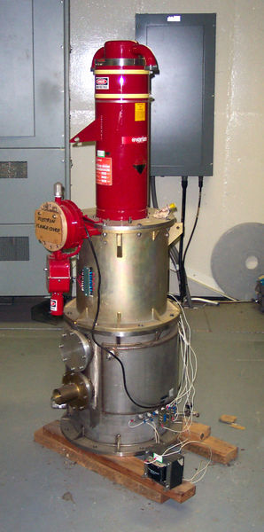
400 kW klystron used for spacecraft communication at the Canberra Deep Space Communications Complex. This is a spare in storage.
5 kW klystron tube used as power amplifier in UHF television transmitter, 1952. When installed, the tube projects through holes in the center of the cavity resonators, with the sides of the cavities making contact with the metal rings on the tube.
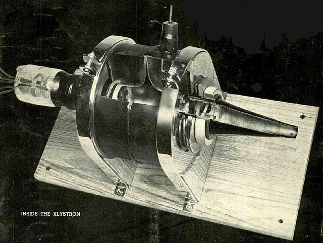
The first commercial klystron, manufactured by Westinghouse in 1940. Part of the tube is cut away to show the internal construction. On the left are the cathode and accelerating anode, which create the electron beam. In the center between the wooden supports is the drift tube, surrounded by the two donut-shaped cavity resonators: the "buncher" and the "catcher". The output terminal is visible at top. On the right is the cone shaped collector anode, which absorbs the electrons. It could generate 200 W of power at a wavelength of 40 centimeters (750 MHz) with 50% efficiency.
Klystron oscillator from 1944. The electron gun is on the right, the collector on the left. The two cavity resonators are in center, linked by a short coaxial cable to provide positive feedback.