Wire wrap is an electronic component assembly technique that was invented to wire telephone crossbar switches, and later adapted to construct electronic circuit boards. Electronic components mounted on an insulating board are interconnected by lengths of insulated wire run between their terminals, with the connections made by wrapping several turns of uninsulated sections of the wire around a component lead or a socket pin.
Close-up of a wire-wrap connection
Typical wire wrap construction of Bell System telephone crossbar switch. Some types of connection were soldered.
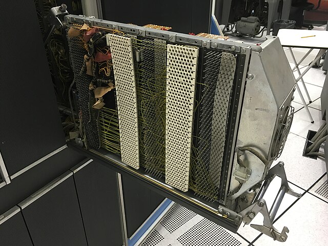
Wire wrapped backplane of an IBM 1401 computer, introduced in 1959
A modern wire wrap in a CFL
A printed circuit board (PCB), also called printed wiring board (PWB), is a medium used to connect or "wire" components to one another in a circuit. It takes the form of a laminated sandwich structure of conductive and insulating layers: each of the conductive layers is designed with a pattern of traces, planes and other features etched from one or more sheet layers of copper laminated onto and/or between sheet layers of a non-conductive substrate. Electrical components may be fixed to conductive pads on the outer layers in the shape designed to accept the component's terminals, generally by means of soldering, to both electrically connect and mechanically fasten them to it. Another manufacturing process adds vias, plated-through holes that allow interconnections between layers.
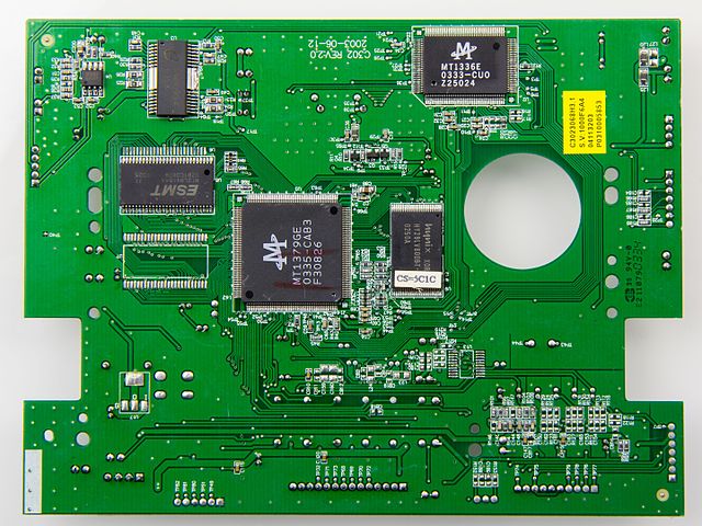
Printed circuit board of a DVD player
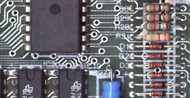
Part of a 1984 Sinclair ZX Spectrum computer board, a printed circuit board, showing the conductive traces, the through-hole paths to the other surface, and some electronic components mounted using through-hole mounting
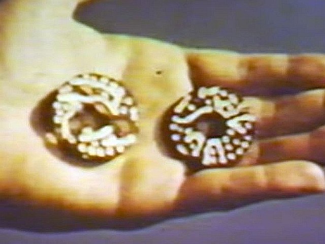
Proximity fuze Mark 53 production line 1944
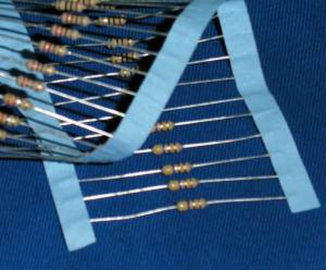
Through-hole (leaded) resistors